Fuel tank removal
- Remove the left and right frame side covers. (9-5)
- Remove the fuel tank mounting bolt.
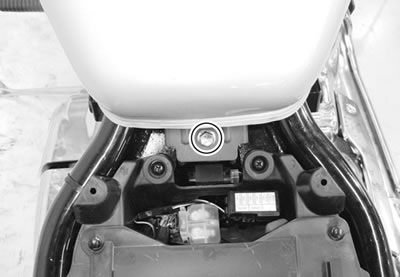
- Lift and support the fuel tank about 10 cm (3.94 in) with the proper stay.
Note: Be careful not to lift the fuel more than about 10 cm (3.94 in), or hoses will be twisted.
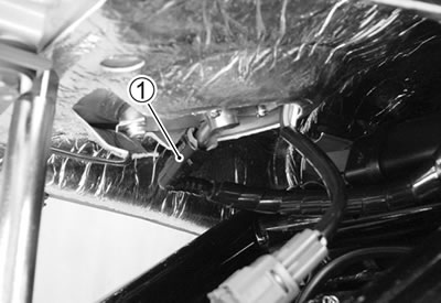
- Disconnect the fuel pump lead wire coupler 1.
- Place a rag under the fuel feed hose and disconnect the fuel feed hose 2.
Caution: When removing the fuel tank, do not leave the fuel feed hose 2 on the fuel tank side.
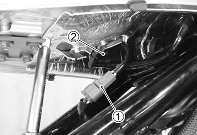
Warning: Gasoline is highly flammable and explosive. Keep heat, spark and flame away.
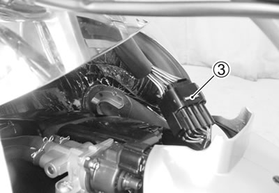
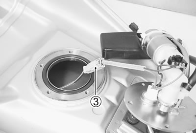
- Disconnect the speedometer coupler 3.
- Remove the fuel tank.
Fuel tank installation
- Installation is in the reverse order of removal.
Fuel pressure inspection
- Lift and support the fuel tank. (6-3)
- Place a rag under the fuel feed hose.
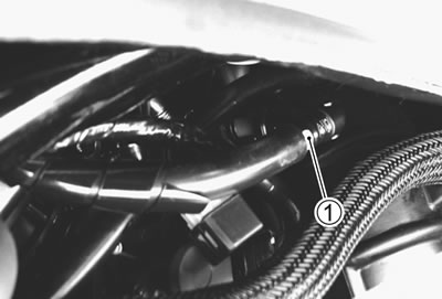
- Disconnect the fuel feed hose 1.
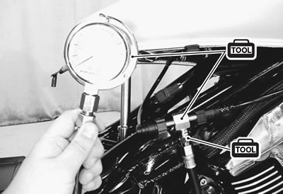
- Install the special tools between the fuel tank and fuel delivery pipe.
- 09940-40211: Fuel pressure gauge adaptor
- 09940-40220: Fuel pressure gauge hose attachment
- 09915-74511: Oil pressure gauge hose
Turn the ignition switch ON and check the fuel pressure.
Fuel pressure: Approx. 300 kPa (3.0 kgf/cm², 43 psi)
If the fuel pressure is lower than the specification, inspect the following items:
- Clogged fuel filter
- Pressure regulator
- Fuel pump
- Fuel hose leakage
If the fuel pressure is higher than the specification, inspect the following items:
- Fuel pump check valve
- Pressure regulator
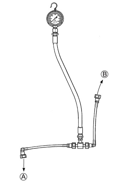
А. To fuel tank; В. To fuel delivery pipe
Warning:
- Before removing the special tools, turn the ignition switch to OFF position and release the fuel pressure slowly.
- Gasoline is highly flammable and explosive. Keep heat, sparks and flame away.
Fuel pump inspection
Turn the ignition switch ON and check that the fuel pump operates for few seconds.
If the fuel pump motor does not make operating sound, inspect the fuel pump circuit connections or inspect the fuel pump relay and tip-over sensor.
If the fuel pump relay, tip-over sensor and fuel pump circuit connections are OK, the fuel pump may be faulty, replace the fuel pump with a new one.
Fuel discharge amount inspection
Warning: Gasoline is highly flammable and explosive. Keep heat, spark and flame away.
- Lift and support the fuel tank. (6-3)
- Place a rag under the fuel feed hose and disconnect the fuel feed hose 1 from the fuel delivery pipe.
- Place the measuring cylinder and insert the fuel feed hose end into the measuring cylinder.
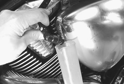
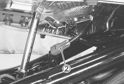
- Disconnect the fuel pump lead wire coupler 2.
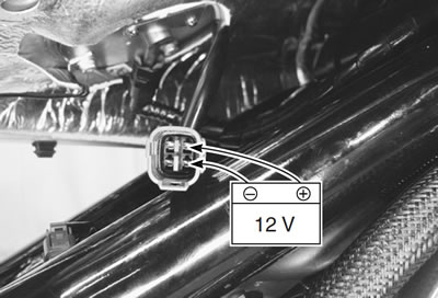
- Connect a proper lead wire into the fuel pump lead wire coupler (fuel pump side) and apply 12 volts to the fuel pump (between Y/R wire and B/W wire) for 10 seconds and measure the amount of fuel discharged.
- Battery + terminal — (Yellow with red tracer)
- Battery − terminal — (Black with white tracer)
If the pump does not discharge the amount specified, it means that the fuel pump is defective or that the fuel filter is clogged.
Fuel discharge amount:
168 ml (5.7/5.9 US/Imp oz) and more/10 sec.
Note: The battery must be in fully charged condition.
Fuel pump relay inspection
Cooling fan relay is located in front of the battery.
- Remove the right side frame cover. (9-5)
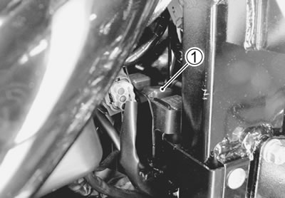
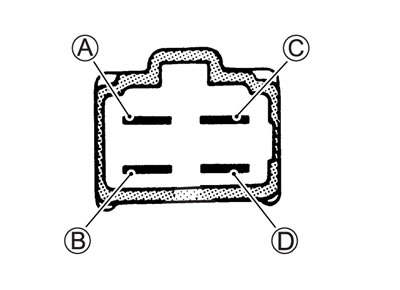
- Remove the fuel pump relay 1.
First check the insulation between А and В terminals with tester. Then apply 12 V to С and D terminals, + to C and − to D, and check the continuity between A and B.
If there is no continuity, replace it with a new one.
- 09900-25008: Multi-circuit tester set
- Tester knob indication: Continuity test (•)))
Fuel pump and fuel level gauge removal
Construction
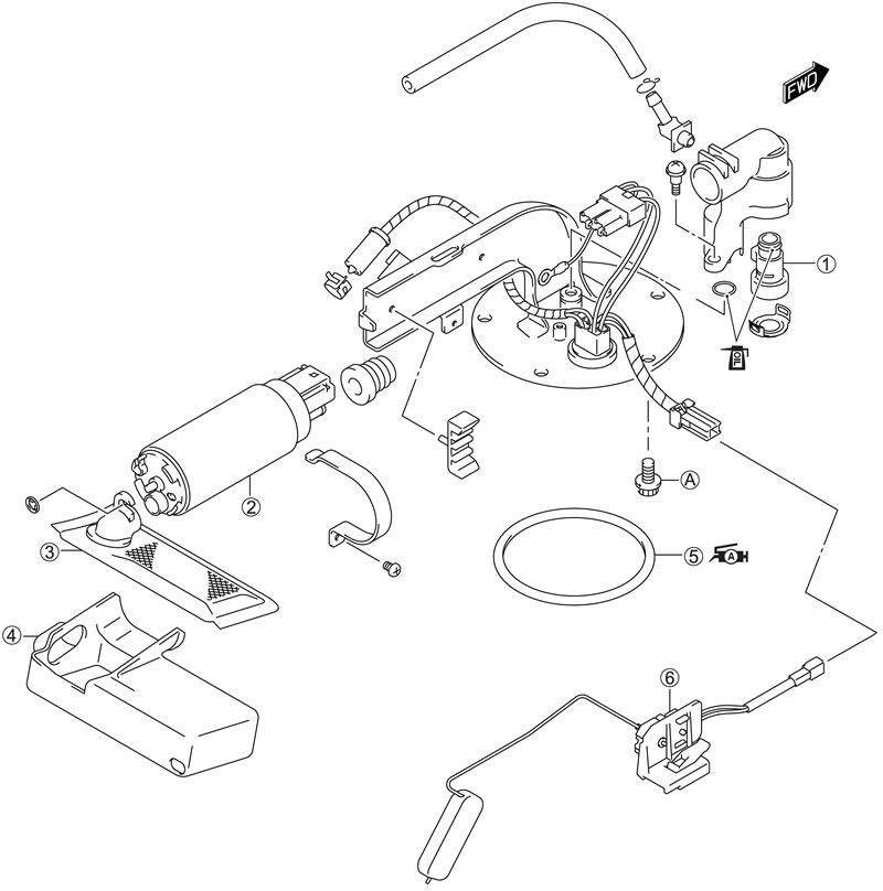
1. Thermistor; 2. Fuel pump; 3. Fuel mesh filter; 4. Filter cover; 5. O-ring; 6. Fuel level gauge; А. Fuel pump mounting bolt
| ITEM | Nm | kgf·m | lb·ft |
| A | 10 | 1.0 | 7.0 |
Removal
- Remove the fuel tank. (6-3)
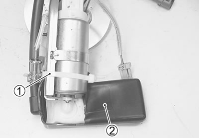
- Remove the fuel tank shield 1.
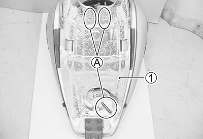
A. Clamp
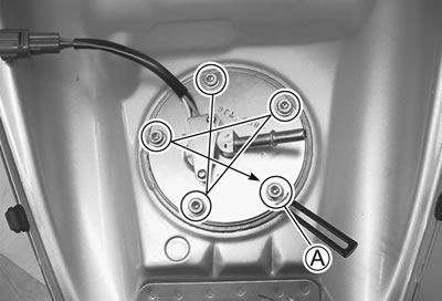
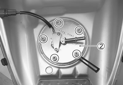
- Remove the fuel pump assembly 2 mounting bolts diagonally.
Warning: Gasoline is highly flammable and explosive. Keep heat, spark and flame away.
- Remove the fuel pump assembly and disconnect the fuel gauge lead wire coupler 3.
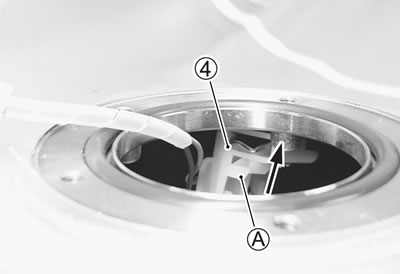
- Remove the fuel level gauge 4 while pushing the pawl end А.
Caution: Do not pull the lead wire when removing the fuel gauge.
Fuel level gauge inspection (10-36).
Fuel pump disassembly
- Disconnect the fuel pump coupler 1.
- Remove the band 2 and clamp 3.
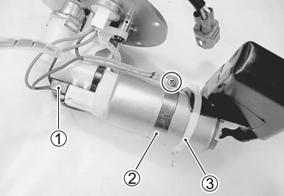
- Remove the hose 4 and filter cover 5.
- Remove the clamp 6 and thermistor 7.
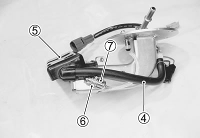
- Remove the fuel mesh filter 8.
- Remove the fuel pump 9.
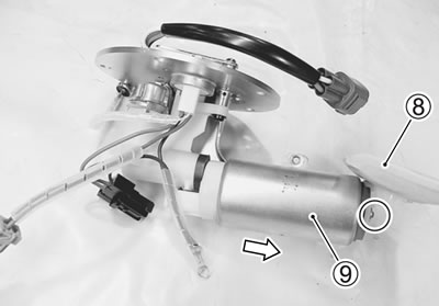
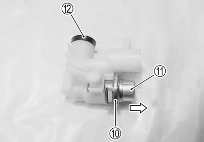
- Remove the clip 10 and pressure regulator 11.
- Remove the bushing 12.
Fuel mesh filter inspection
- Disconnect the clamp 1 and rubber boot 2.
If the fuel mesh filter is clogged with sediment or rust, replace the fuel filter with a new one.
Fuel pump and fuel level gauge
Reassembly and installation
Install the fuel pump and fuel level gauge in the reverse order of removal and disassembly. Pay attention to the following points:
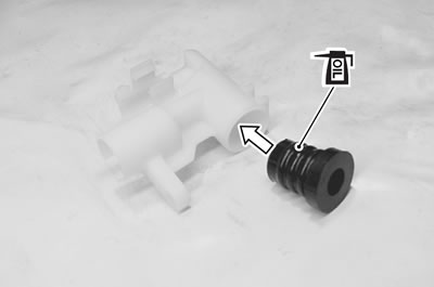
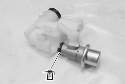
- Apply thin coat of engine oil to the new bushing and install if to the fuel joint pipe.
Caution: Use the new bushing to prevent fuel leakage.
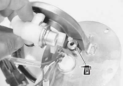
- Install the new O-ring to the pressure regulator.
- Apply thin coat of the engine oil to the new O-ring.
Caution: Use the new O-ring to prevent fuel leakage.
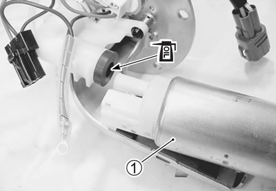
- Install the new O-ring to the fuel pipe.
- Apply thin coat of the engine oil to the new O-ring.
Caution: Use the new O-ring to prevent fuel leakage.
- Apply thin coat of the engine oil to the bushing.
- Install the fuel pump 1.
- Install a new O-ring and apply SUZUKI SUPER GREASE "A" to it.
- 99000-25010: SUZUKI SUPER GREASE "A" or equivalent

Warning: The O-ring must be replaced with a new one to prevent fuel leakage.
- When installing the fuel pump assembly, first tighten all the fuel pump mounting bolts lightly and then to the specified torque as shown.
Fuel pump mounting bolt: 10 Nm (1.0 kgf·m, 7.0 lb·ft)
Note: Fit the clamp bolt А.