| DETECTED CONDITION | POSSIBLE CAUSE | ||
| C46 | The operation signal does not reach the EXCV actuator. EXCVA position sensor voltage low or high 0.1 V ≤ Sensor voltage < 4.9 V (without the above range) | EXCVA maladjusted EXCVA circuit open or short EXCVA motor malfunction EXCVA position sensor malfunction | |
| P1657 | H | Sensor voltage is higher than specified value. | EXCVA position sensor circuit shorted to VCC or ground circuit open |
| L | Sensor voltage is lower than specified value. | EXCVA position sensor circuit open or shorted to ground or VCC circuit open | |
| P1658 | The operation signal does not reach the EXCVA motor. ECM does not receive communication signal from the STVA motor. | EXCVA motor circuit open or short EXCVA motor malfunction | |
Inspection
Step 1 (When indicating C46:)
- 1) Turn the ignition switch OFF.
- 2) Remove the lower frame cover. (7-8)
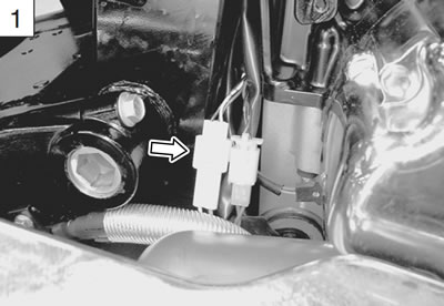
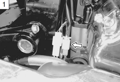
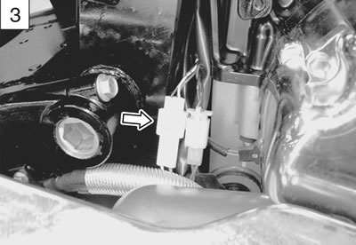
- 3) Check the EXCVA lead wire coupler for loose or poor contacts.

- 4) Turn the ignition switch ON.
- 5) Check the operation of the EXCVA. (EXCVA operating order: Full close → Full open → 30% open)
Note: Install the EXCVA rubber cover correctly after checking the EXCVA.
Is the operation OK?
| YES | Go to Step 2. |
| NO | Go to Step 6. |
Step 1 (When indicating P1657-H:)
- 1) Turn the ignition switch OFF.
- 2) Remove the lower frame cover. (7-8)
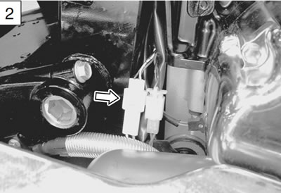
- 3) Check the EXCVA position sensor coupler for loose or poor contacts.
If OK, then check the EXCVA position sensor lead wire continuity.
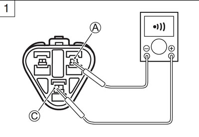
- 4) Disconnect the EXCVA position sensor coupler.
- 5) Check the continuity between Red wire С and Yellow wire А.
If the sound is not heard from the tester, the circuit condition is OK.
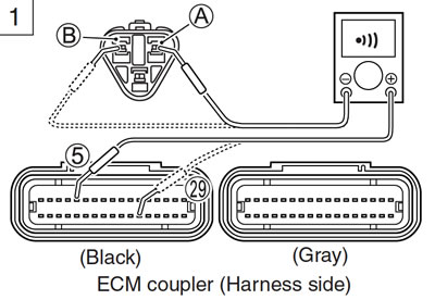
- 6) Disconnect the ECM coupler. (5-37)
- 7) Check the continuity between Yellow wire А and terminal 5.
- 8) Also, check the continuity between B/Br wire В and terminal 29.
Caution: When using the multi-circuit tester, do not strongly touch the terminal of the ECM coupler with a needle pointed tester probe to prevent the terminal damage or terminal bend.
- EXCVA lead wire continuity: Continuity (•)))
- 09900-25008: Multi-circuit tester set
- 09900-25009: Needle pointed probe set
- Tester knob indication: Continuity test (•)))
Is the continuity OK?
| YES | Go to Step 4. |
| NO | Yellow wire shorted to VCC, or B/Br wire open |
- 9) After repairing the trouble, clear the DTC using SDS tool. (5-26)
Step 1 (When indicating P1657-L:)
- 1) Turn the ignition switch OFF.
- 2) Remove the lower frame cover. (7-8)
- 3) Check the EXCVA position sensor coupler for loose or poor contacts.
If OK, then check the EXCVA position sensor lead wire continuity.

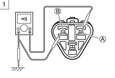
- 4) Disconnect the EXCVA position sensor coupler.
- 5) Check the continuity between Yellow wire А and ground.
- 6) Also, check the continuity between Yellow wire А and B/Br wire В. If the sound is not heard from the tester, the circuit condition is OK.
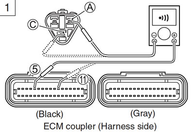
- 7) Disconnect the ECM coupler. (5-37)
- 8) Check the continuity between Yellow wire А and terminal 5.
- 9) Also, check the continuity between Red wire С and terminal 11.
Caution: When using the multi-circuit tester, do not strongly touch the terminal of the ECM coupler with a needle pointed tester probe to prevent the terminal damage or terminal bend.
- EXCVA lead wire continuity: Continuity (•)))
- 09900-25008: Multi-circuit tester set
- 09900-25009: Needle pointed probe set
- Tester knob indication: Continuity test (•)))
Is the continuity OK?
| YES | Go to Step 2 and Go to Step 4. |
| NO | Red or Yellow wire open, or Yellow wire shorted to ground |
- 10) After repairing the trouble, clear the DTC using SDS tool. (5-26)
Step 1 (When indicating P1658:)
- 1) Turn the ignition switch OFF.
- 2) Remove the lower frame oupler for loose or poor contacts.
Is the contacting OK?
| YES | Go to Step 6. |
| NO | Loose or poor contacts on the EXCV motor coupler |
- 4) After repairing the trouble, clear the DTC using SDS tool. (5-26)
Step 2
- 1) Turn the ignition switch OFF.
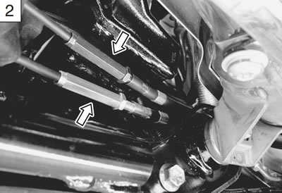
- 2) Check the installation of EXCV cables. (7-12)
If it is necessary, adjust the EXCV cables. (7-4)
- 3) Disconnect the EXCVA position sensor lead wire coupler.
- 4) Turn the ignition switch ON.
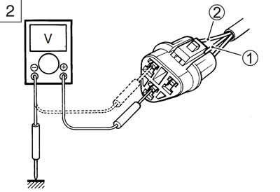
- 5) Measure the voltage between the Red wire terminal 1 and ground.
- 6) If OK, then measure the voltage between the Red wire terminal 1 and B/Br wire terminal 2.
- Position sensor input voltage: 4.5 - 5.5 V
- (+ Red - − Ground)
- (+ Red - − B/Br)
- 09900-25008: Multi circuit tester set
- Tester knob indication: Voltage
Is the voltage OK?
| YES | Go to Step 3. |
| NO | Loose or poor contacts on the ECM coupler (terminal 11 or 29) Open or short circuit in the Red wire or B/Br wire |
- 7) After repairing the trouble, clear the DTC using SDS tool. (5-26)
Step 3
- 1) Turn the ignition switch OFF.
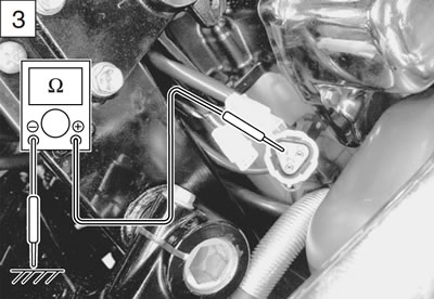
- 2) Check the continuity between Yellow wire and ground.
- Position sensor continuity: ∞ Ω (Infinity)
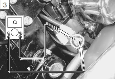
- 3) If OK, then measure the position sensor resistance.
- 4) Connect the position sensor coupler.
- 5) Set the EXCVA to adjustment position. (7-2)
- 6) Disconnect the position sensor coupler and measure the resistance. (between Yellow and White wires)
- Position sensor resistance at adjustment position: Approx. 3.1 kΩ (+ Yellow - − White)
- 09900-25008: Multi circuit tester set
- Tester knob indication: Resistance (Ω)
Is the resistance OK?
| YES | Go to Step 4. |
| NO | Replace the EXCVA with a new one. |
Step 4
- 1) Turn the ignition switch OFF.
- 2) Connect the position sensor coupler.
- 3) Measure the position sensor output voltage at fully close position and fully open position.
- 4) Insert the needle pointed probes to the back side of the position sensor lead wire coupler. (+ Yellow - − B/Br)
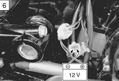
- 5) Disconnect the EXCVA motor lead wire coupler.
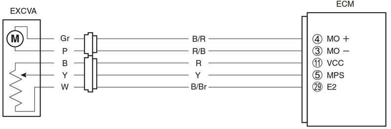
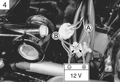
- 6) To set the EXCV to fully close position, apply 12 volts to А and В terminals.
- Positive wire - А (Pink wire) terminal
- Negative wire - В (Gray wire) terminal
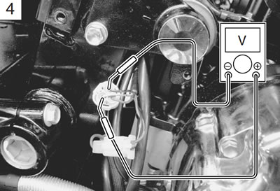
- 7) Turn the ignition switch ON.
- 8) Measure the position sensor output voltage at fully close position.
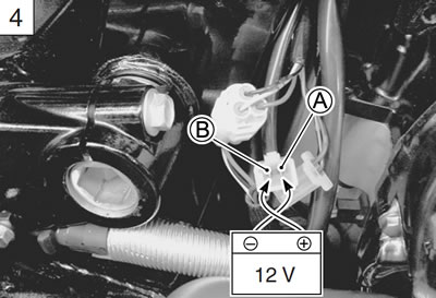
- 9) Then, to set the EXCV to fully open position, apply 12 volts to В and А terminals.
- Positive wire - В (Gray wire) terminal
- Negative wire - А (Pink wire) terminal
- 10) Measure the position sensor output voltage at fully open position.
Position sensor output voltage:
- EXCV is fully close: 0.5 - 1.5 V
- EXCV is fully open: 3.5 - 4.5 V
- (+ Yellow - − B/Br)
- 09900-25008: Multi circuit tester set
- 09900-25009: Needle pointed probe set
- Tester knob indication: Voltage
Is the voltage OK?
| YES | Replace the ECM with a known good one, and inspect it again. |
| NO | Go to Step 5. |
- 11) After repairing the trouble, clear the DTC using SDS tool. (5-26)
Step 5
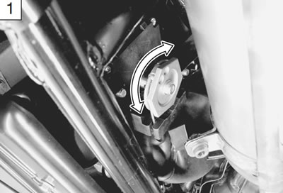
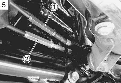
- 1) If the position sensor output voltage is 0.5 V and less at fully close position, adjust the output voltage to specified by turning out the No. 1 cable adjuster 1.
- 2) Repeat the above procedure (Step 4) until the out put voltage becomes specified value. (If C46/P1657 code is indicated after adjusting the voltage, increase the voltage to 0.4 V.)
Caution:
- Adjusting the cable with the EXCV fully opened or fully closed can damage the EXCVA. Be sure to adjust the cable with the EXCV set in adjustment position. (7-2)
- Do not turn the EXCVA pulley using the wrench.
- 3) If the position sensor output voltage is 4.5 V and more at fully open position, adjust the output voltage to specified by turning out the No. 2 cable adjuster 2.
Repeat the above procedure (Step 4) until the output voltage is within the specified value.
Position sensor output voltage:
- EXCV is fully close: 0.5 Output Voltage 1.5
- EXCV is fully open : 3.5 Output Voltage 4.5
Is the voltage OK?
| YES | Replace the ECM with a known good one, and inspect it again. |
| NO | Replace the EXCVA with a new one. |
- 3) After repairing the trouble, clear the DTC using SDS tool. (5-26)
Step 6
- 1) Turn the ignition switch OFF.
- 2) Disconnect the motor lead wire coupler of the EXCVA.

- 3) Apply 12 volts to the terminal and check the operation of EXCVA.
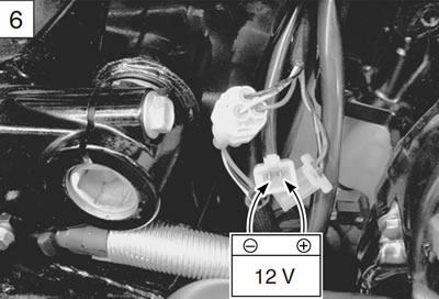
- 4) Then, swap the wires supplied 12 volts and check the operation of EXCVA. (Check the operation of EXCVA both way.)
Is the operation OK?
| YES | Loose or poor contacts on the EXCVA or ECM coupler (terminal 3 or 4) Open or short circuit in the B/R wire or R/B wire If wire and connection are OK, intermittent trouble or faulty ECM. Recheck each terminal and wire harness for open circuit and poor connection. Replace the ECM with a known good one, and inspect it again. |
| NO | Replace the EXCVA with a new one. Inspect that the EXCV and two cables move smoothly. (7-3) |
- 5) After repairing the trouble, clear the DTC using SDS tool. (5-26)
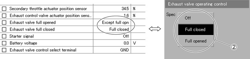
Active control
- 1) Set up the SDS tool. (Refer to the SDS operation manual for further details.)
- 2) Turn the ignition switch ON.
- 3) Click "Exhaust valve operating control" 1.
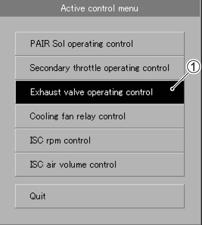
- 4) Click each button 2.
At this time, if an operation sound is heard from the EXCVA, the function is normal.