
| DETECTED CONDITION | POSSIBLE CAUSE | ||
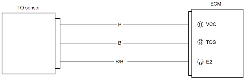
| C23 | The sensor voltage should be the following for 2 sec. and more, after ignition switch is turned ON | TO sensor circuit open or short TO sensor malfunction | |
| P1651 | 0.2 V ≤ Sensor voltage < 4.8 V | ECM malfunction | |
| P1651 | H | Sensor voltage is higher than specified value. | TO sensor circuit shorted to VCC or ground circuit open |
| L | Sensor voltage is lower than specified value. | TO sensor circuit open or shorted to ground or VCC circuit open | |
Inspection
Step 1 (When indicating C23:)
- 1) Turn the ignition switch OFF.
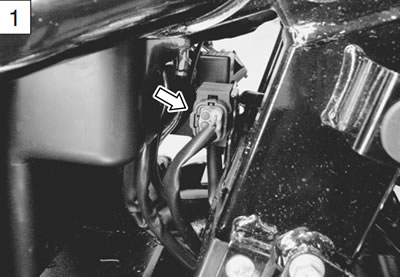
- 2) Remove the fuel tank. (6-3)
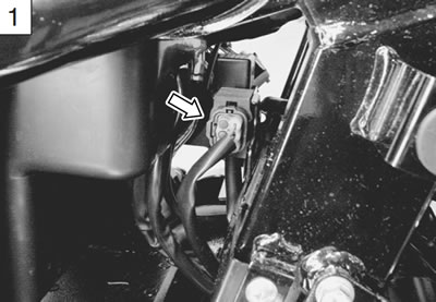
- 3) Check the TO sensor coupler for loose or poor contacts. If OK, then measure the TO sensor resistance.
- 4) Disconnect the TO sensor coupler.
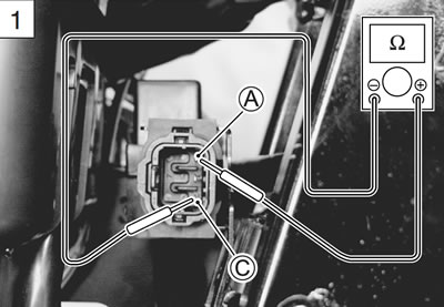
- 5) Measure the resistance between terminal А and terminal С.
- TO sensor resistance: 16.5 - 22.3 kΩ
- (Terminal А - Terminal С)
- 09900-25008: Multi-circuit tester set
- Tester knob indication: Resistance (Ω)
Is the resistance OK?
| YES | Go to Step 2. |
| NO | Replace the TO sensor with a new one. |
Step 1 (When indicating P1651-H:)
- 1) Turn the ignition switch OFF.
- 2) Remove the fuel tank. (6-3)
- 3) Check the TO sensor coupler for loose or poor contacts. If OK, then check the TO sensor lead wire continuity.

- 4) Disconnect the TO sensor coupler.
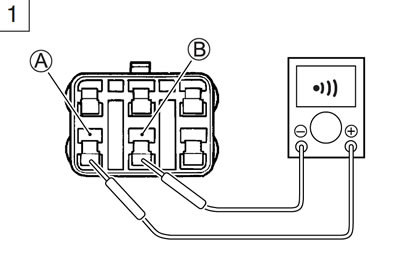
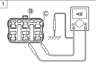
- 5) Check the continuity between Red wire А and Black wire В.
If the sound is not heard from the tester, the circuit condition is OK.
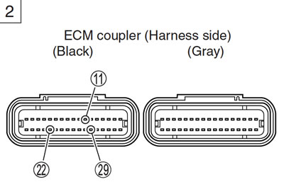
- 6) Disconnect the ECM coupler. (5-37)
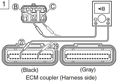
- 7) Check the continuity between Black wire В and terminal 22.
- 8) Also, check the continuity between B/Br wire С and terminal 29.
Caution: When using the multi-circuit tester, do not strongly touch the terminal of the ECM coupler with a needle pointed tester probe to prevent the terminal damage or terminal bend.
- TOS lead wire continuity: Continuity (•)))
- 09900-25008: Multi-circuit tester set
- 09900-25009: Needle pointed probe set
- Tester knob indication: Continuity test (•)))
Is the continuity OK?
| YES | Go to Step 2. |
| NO | Black wire shorted to VCC, or B/Br wire open. |
- 9) After repairing the trouble, clear the DTC using SDS tool. (5-26)
Step 1 (When indicating P1651-L:)
- 1) Turn the ignition switch OFF.
- 2) Remove the fuel tank. (6-3)
- 3) Check the TO sensor coupler for loose or poor contacts. If OK, then check the TO sensor lead wire continuity.
- 4) Disconnect the TO sensor coupler.
- 5) Check the continuity between Black wire В and ground.
- 6) Also, check the continuity between Black wire В and B/Br wire С. If the sound is not heard from the tester, the circuit condition is OK.
- 7) Disconnect the ECM coupler. (5-37)
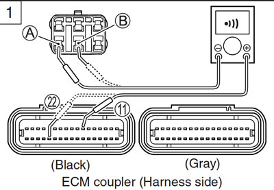
- 8) Check the continuity between Red wire А and terminal 11.
- 9) Also, then check the continuity between Black wire В and terminal 22.
CAUTION: When using the multi-circuit tester, do not strongly touch the terminal of the ECM coupler with a needle pointed tester probe to prevent the terminal damage or terminal bend.
- TOS lead wire continuity: Continuity (•)))
- 09900-25008: Multi-circuit tester set
- 09900-25009: Needle pointed probe set
- Tester knob indication: Continuity test (•)))
Is the continuity OK?
| YES | Go to Step 2. |
| NO | Red or Black wire open, or Black wire shorted to ground. |
- 10) After repairing the trouble, clear the DTC using SDS tool. (5-26)
Step 2
- 1) Connect the TO sensor coupler and ECM coupler.
- 2) Insert the needle pointed probes to the lead wire coupler.
- 3) Turn the ignition switch ON.
- 4) Measure the voltage at the wire side coupler between Black and B/Br wires.
- TO sensor voltage (Normal): 0.4 - 1.4 V (+ Black - − B/Br)
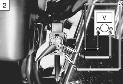
Also, measure the voltage when leaning the motorcycle.
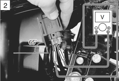
- 5) Dismount the TO sensor from its bracket and measure the voltage when it is leaned 65° and more, left and right, from the horizontal level.
- TO sensor voltage (Leaning): 3.7 - 4.4 V (+ Black - − B/Br)
- 09900-25008: Multi-circuit tester set
- 09900-25009: Needle pointed probe set
- Tester knob indication: Voltage
Is the voltage OK?
| YES | Red, Black or B/Br wire open or shorted to ground, or poor 11, 22 or 29 connection If wire and connection are OK, intermittent trouble or faulty ECM. Recheck each terminal and wire harness for open circuit and poor connection. Replace the ECM with a known good one, and inspect it again. |
| NO | Loose or poor contacts on the ECM coupler Open or short circuit Replace the TO sensor with a new one. |
- 6) After repairing the trouble, clear the DTC using SDS tool. (5-26)
"C24" (P0351), "C25" (P0352), "C26" (P0353) or "C27" (P0354) Ignition system malfunction
When indicating C24/P0351 and C26/P0353 for #1
When indicating C25/P0352 and C27/P0354 for #2
Refer to the IGNITION SYSTEM for details. (10-22)