
| DETECTED CONDITION | POSSIBLE CAUSE | ||
| C13/C17 | IAP sensor voltage is not within the following range. 0.5 V Sensor voltage < 4.85 V | Clogged vacuum passage between throttle body and IAP sensor. Air being drawn from vacuum passage between throttle body angged vacuum passage between throttle body and IAP sensor. Air being drawn from vacuum passage between throttle bodyd IAP sensor. IAP sensor circuit open or shorted to ground | |
| P1750/ P0105 | Note that atmospheric pressure varies depending on weather conditions as well as altitude. Take that into consideration when inspecting voltage. | IAP sensor malfunction. ECM malfunction. | |
| P1750/ P0105 | H | Sensor voltage is higher than specified value. | IAP sensor circuit shorted to VCC or ground circuit open. IAP sensor circuit open or shorted to ground or VCC circuit open. |
| L | Sensor voltage is lower than specified value. | ||
Inspection
Step 1
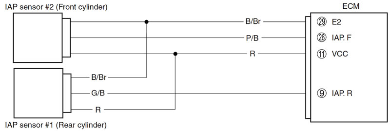
When indicating C13 for IAP sensor #2
When indicating C17 for IAP sensor #1
- 1) Remove the fuel tank. (6-3)
- 2) Turn the ignition switch OFF.
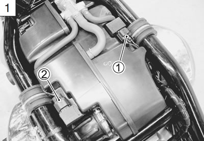
- 3) Check the IAP sensor coupler (#2 1 or #1 2) for loose or poor contacts.
If OK, then measure the IAP sensor input voltage.
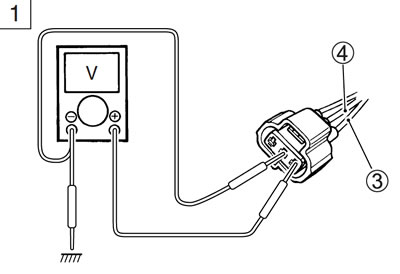
- 4) Disconnect the IAP sensor coupler.
- 5) Turn the ignition switch ON.
- 6) Measure the voltage at the Red wire 3 and ground.
- 7) If OK, then measure the voltage at the Red wire 3 and B/Br wire 4.
IAP sensor input voltage: 4.5 - 5.5 V
- (+ Red - − Ground)
- (+ Red - − B/Br)
- 09900-25008: Multi-circuit tester set
- Tester knob indication: Voltage
Is the voltage OK?
| YES | Go to Step 2. |
| NO | Loose or poor contacts on the ECM coupler (terminal 11 or 29). Open or short circuit in the Red wire or B/Br wire. |
- 8) After repairing the trouble, clear the DTC using SDS tool. (5-26)
Step 2
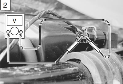
- 1) Connect the IAP sensor coupler.
- 2) Reinstall the fuel tank and lift up fuel tank.
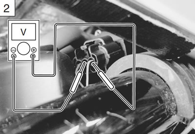
- 3) Insert the needle pointed probes to the lead wire coupler.
- 4) Start the engine at idle speed and measure the IAP sensor output voltage at the wire side coupler.
- (#2: between P/B and B/Br wires)
- (#1: between G/B and B/Br wires)
IAP sensor output voltage:
- Approx. 2.6 V at idle speed (#2: + P/B - − B/Br) (#1: + G/B - − B/Br)
- 09900-25008: Multi-circuit tester set
- 09900-25009: Needle pointed probe set
- Tester knob ation: Voltage
Is the voltage OK?
| YES | Go to Step 3. |
| NO | Check the vacuum hose for crack or damage. Open or short circuit in the P/B wire. (#2) Open or short circuit in the G/B wire. (#1) If vacuum hose and wire are OK, replace the IAP sensor with a new one. |
- 5) After repairing the trouble, clear the DTC using SDS tool. (5-26)
Step 3
- 1) Turn the ignition switch OFF.
- 2) Remove the IAP sensor. (6-13)
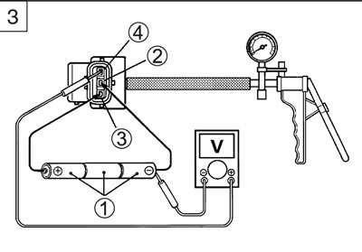
- 3) Connect the vacuum pump gauge to the vacuum port of the IAP sensor.
- 4) Arrange 3 new 1.5 V batteries in series 1 (check that total - voltage is 4.5 - 5.0 V) and connect − terminal to the ground - terminal 2 and + terminal to the VCC terminal 3.
- 5) Check the voltage between Vout terminal 4 and ground 2. Also, check if voltage reduces when vacuum is applied up to 400 mmHg by using vacuum pump gauge. (5-40)
- 09917-47011: Vacuum pump gauge
- 09900-25008: Multi-circuit tester set
- Tester knob indication: Voltage
Is the voltage OK?
| YES | Red, P/B or B/Br wire open or shorted to ground, or poor 11, 26 or 29 connection (#2) G/B, Red or B/Br wire open or shorted to ground, or poor 9, 11 or 29 connection (#1) If wire and connection are OK, intermittent trouble or faulty ECM. Recheck each terminal and wire harness for open circuit and poor connection. Replace the ECM with a known good one, and inspect it again. |
| NO | If check result is not satisfactory, replace the IAP sensor with a new one. |
- 6) After repairing the trouble, clear the DTC using SDS tool. (5-26)
Step 1
When indicating P1750-H for IAP sensor #2
When indicating P0105-H for IAP sensor #1
- 1) Turn the ignition switch OFF.
- 2) Remove the fuel tank. (6-3)
- 3) Check the IAP sensor coupler for loose or poor contacts. If OK, then check the IAP sensor lead wire continuity.
- 4) Disconnect the IAP sensor coupler.
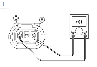
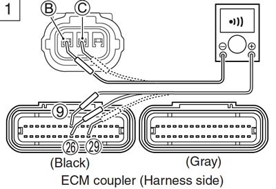
- 5) Check the continuity between Red wire А and P/B (#2 1) or G/B (#1 2) wire В.
If the sound is not heard from the tester, the circuit condition is OK.
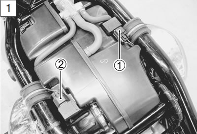
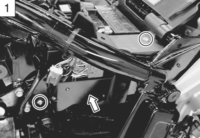
- 6) Remove the left frame lower side cover. (3-6)
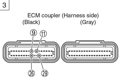
- 7) Remove the ECM bracket and disconnect the ECM coupler.
- 8) Check the continuity between P/B wire В and terminal 9 (#2), and G/B wire В and terminal 26 (#1).
- 9) If OK, then check the continuity between B/Br wire С (#1 and #2) and terminal 29.
Caution: When using the multi-circuit tester, do not strongly touch the terminal of the ECM coupler with a needle pointed tester probe to prevent the terminal damage or terminal bend.
- IAPS lead wire continuity: Continuity(•)))
- 09900-25008: Multi-circuit tester set
- 09900-25009: Needle pointed probe set
- Tester knob indication: Continuity test (•)))
Is the continuity OK?
| YES | Go to Step 2. |
| NO | G/B or P/B wire shorted to VCC, or B/Br wire open. |
- 10) After repairing the trouble, clear the DTC using SDS tool. (5-26)
Step 1
When indicating P1750-L for IAP sensor #2
When indicating P0105-L for IAP sensor #1
- 1) Turn the ignition switch OFF.
- 2) Remove the fuel tank. (6-3)
- 3) Check the IAP sensor coupler for loose or poor contacts. If OK, then check the IAP sensor lead wire continuity.

- 4) Disconnect the IAP sensor coupler.
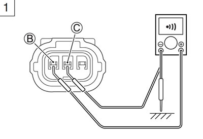
- 5) Check the continuity between P/B (#2 1) or G/B (#1 2) wire В and ground.
- 6) Also, check the continuity between P/B or G/B wire В and B/Br wire С. If the sound is not heard from the tester, the circuit condition is OK.
- 7) Disconnect the ECM coupler. (5-37)
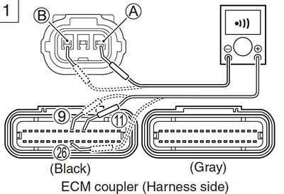
- 8) Check the continuity between Red wires А (#1 and #2) and terminal 11.
- 9) Also, check the continuity between P/B wire В and terminal 9, and G/B wire В and terminal 26.
Caution: When using the multi-circuit tester, do not strongly touch the terminal of the ECM coupler with a needle pointed tester probe to prevent the terminal damage or terminal bend.
- IAPS lead wire continuity: Continuity (•)))
- 09900-25008: Multi-circuit tester set
- 09900-25009: Needle pointed probe set
- Tester knob indication: Continuity test (•)))
Is the continuity OK?
| YES | Go to Step 1 (5-34) and go to Step 2. |
| NO | Red wire and P/B or G/B wire open, or P/B and G/B wire shorted to ground |
- 10) After repairing the trouble, clear the DTC using SDS tool. (5-26)
Step 2
- 1) Connect the IAP sensor coupler and ECM coupler.
- 2) Reinstall the fuel tank and lift up the fuel tank.
- 3) Insert the needle pointed probes to the lead wire coupler.
- 4) Start the engine at idle speed and measure the IAP sensor output voltage at the wire side coupler.
- (#2: between P/B and B/Br wires)
- (#1: between G/B and B/Br wires)
IAP sensor output voltage:
- Approx. 1.4 - 3.8 V at idle speed (#2: + P/B - − B/Br) (#1: + G/B - − B/Br)
- 09900-25008: Multi-circuit tester set
- 09900-25009: Needle pointed probe set
- Tester knob indication: Voltage
Is the voltage OK?
| YES | Go to Step 3. NO | Check the vacuum hose for crack or damage. Open or short circuit in the P/B wire. (#2) Open or short circuit in the G/B wire. (#1) If vacuum hose and wire are OK, replace the IAP sensor with a new one. |
- 5) After repairing the trouble, clear the DTC using SDS tool. (5-26)
Step 3 (5-36)
Output voltage (VCC voltage 4.5-5.0 V, ambient temp. 20-30°C, 68-86°F)
| ALTITUDE (Reference) | ATMOSPHERIC PRESSURE | OUTPUT VOLTAGE | ||
| (ft) | (m) | (mmHg) | kPa | (V) |
| 0 − 2 000 | 0 − 610 | 760 − 707 | 100 − 94 | 3.4 − 4.0 |
| 2 001 − 5 000 | 611 − 1 524 | 707 − 634 | 94 − 85 | 3.0 - 3.7 |
| 5 001 − 8 000 | 1 525 − 2 438 | 634 − 567 | 85 − 76 | 2.6 − 3.4 |
| 8 001 − 10 000 | 2 439 − 3 048 | 567 − 526 | 76 − 70 | 2.4 - 3.1 |