Note:
- Valve clearance adjustment should be made on a cold engine, at room temperature.
- When the valve clearance is to be measured or adjusted, the piston must be at top dead center (TDC) on the compression stroke.
1. Remove:
- rider's seat
- fuel tank. Refer to "Fuel tank and seats".
2. Disconnect: spark plug caps
3. Remove: spark plugs
4. Remove: air intake box (1)
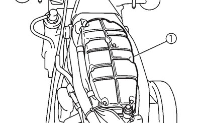
5. Remove:
- cylinder head cover (rear cylinder) (1)
- cylinder head cover (front cylinder)
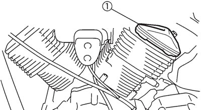
6. Remove: tappet covers (1)

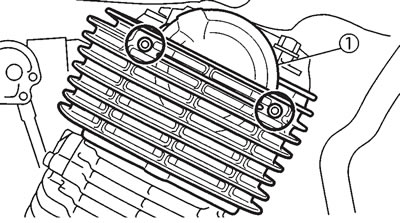
7. Remove:
- camshaft sprocket cover (rear cylinder) (1)
- camshaft sprocket cover (front cylinder)
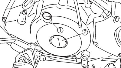
8. Remove:
- timing plug (1)
- straight plug (2)
9. Measure: valve clearance
- Out of specification → Adjust.
Valve clearance (cold):
- Intake valve: 0.07-0.12 mm
- Exhaust valve: 0.12-0.17 mm
a. Turn the crankshaft counterclockwise.
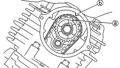
b. When the piston is at TDC on the compression stroke, align either the camshaft sprocket plate hole (a) with the stationary pointer (b) on the cylinder head. When the camshaft sprocket plate hole or camshaft sprocket punch mark is aligned with the stationary pointer, the piston is at top dead center (TDC).
c. Align the TDC mark (c) on the generator rotor with the stationary pointer (d) on the crankcase.
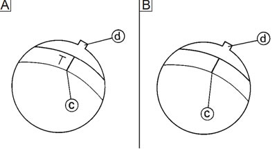
[A] Rear cylinder ("TI" mark); [B] Front cylinder ("I" mark)
d. Measure the valve clearance with a thickness gauge (1).
e. Turn the crankshaft crockwise 290°, and then measure the front cylinder.

10. Adjust valve clearance.
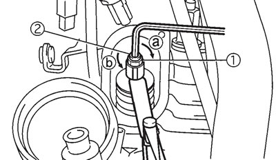
a. Loosen the locknut (1).
b. Insert a thickness gauge between the end of the adjusting screw and the valve tip.
c. Turn the adjusting screw (2) in direction (a) or (b) until the specified valve clearance is obtained.
- Direction (a) — Valve clearance is decreased.
- Direction (b) — Valve clearance is increased.
d. Hold the adjusting screw to prevent it from moving and tighten the locknut to specification.
- Locknut: 27 Nm (2.7 m·kg)
e. Measure the valve clearance again.
f. If the valve clearance is still out of specification, repeat all of the valve clearance adjustment steps until the specified clearance is obtained.
11. Install: all removed parts
Note: Install all removed parts in the reverse order of their disassembly. Note the following points.
- camshaft sprocket covers — 10 Nm (1.0 m·kg)
- tappet covers — 10 Nm (1.0 m·kg)
- spark plugs — 20 Nm (2.0 m·kg)
