Removing oil pump

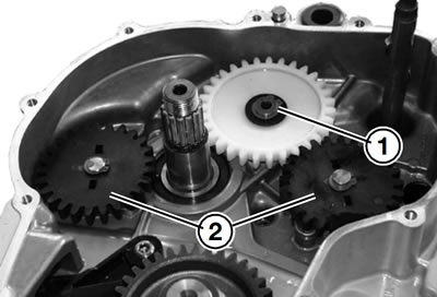
Remove circlip (1) from idler gear.
Remove the retaining rings of the oil-pump gears (2) and disengage the oil-pump gears.

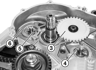
Remove idler gear (3).
Remove needle rollers (4).
Remove thrust washers (5).
Remove countersunk screws from cover and lift off cover (6).
Inspecting oil pump
Using feeler gauges, measure the clearance between the inner and outer rotors and between the outer rotor and the housing.
Permissible face runouts between:
- Inner and outer rotor: max. 0.25 mm (0.010 in)
- Radial clearance: max. 0.25 mm (0.010 in)
- Axial clearance between rotors and cover: max. 0.25 mm (0.010 in)
Installing oil pump

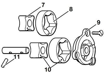
7. Inner rotor; 8. Outer rotor; 9. Cover; 10. Markings; 11. Needle roller
Installation is the reverse of the removal procedure: pay particular attention to the following.
Note: Markings (5) must be visible.
Oil the inner and outer rotors.
Clean the threads of the countersunk screws and coat with Loctite 243.
Tightening torque:
- Countersunk screws in oil-pump cover (clean threads + Loctite 243): 6 Nm
