
Prepare
1. Remove front belt guard. See Belt guards.
2. Disconnect negative battery cable. See Power disconnect.
3. Lift rear of fuel tank. See Lift rear of fuel tank.
4. Remove exhaust system. See Exhaust system.
5. Remove air cleaner assembly. See Air cleaner assembly.
6. Remove breather hoses. See Breather hoses.
7. Remove induction module. See Induction module.
8. Remove cylinder head covers. See Cylinder head covers.
9. Remove clutch cover. See Clutch cover.
10. Remove crankshaft gear. See Crankshaft gear.
11. Remove alternator. See Removing and installing alternator.
12. Remove cam sprocket and timing chain. See Camshaft sprocket and timing chain.
13. Remove cylinder head. See Cylinder heads.
14. Remove chain guides. See Chain guide.
15. Remove cylinder. See Removing and installing cylinders.
Remove
Notice: Handle piston with extreme care. The alloy used in these pistons is very hard. Any scratches, gouges or other marks in the pistons could score the cylinder during engine operation and cause engine damage.
1. See Figure 4-25. Remove piston.
- a. Remove circlip (4).
- b. Remove piston pin (6).
- c. Remove piston (8) from connecting rod (7).
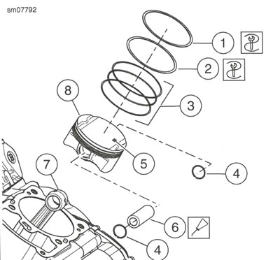
Figure 4-25. Piston: 1. Compression ring; 2. Tapered ring; 3. Three-piece oil control ring; 4. Circlip (2); 5. EX markings; 6. Piston pin; 7. Connecting rod; 8. Piston
Install
Notice: Handle piston with extreme care. The alloy used in these pistons is very hard. Any scratches, gouges or other marks in the pistons could score the cylinder during engine operation and cause engine damage.
1. See Figure 4-26. Install circlip on one side of piston.
- a. Install piston circlip (1).
- b. Verify circlip end gap (3) is not aligned with piston cut-out (2).
Note: Verify EX (exhaust) markings are oriented to the exhaust port of an assembled engine.
2. See Figure 4-25. Install piston.
- a. Position piston (8) on connecting rod (7) so EX markings (5) are aligned to the exhaust port of an assembled engine.
- b. Lubricate piston pin (6) with oil and install piston pin.
- c. Install circlip (4).
- d. Verify smooth movement of the piston and piston pin on the connecting rod.
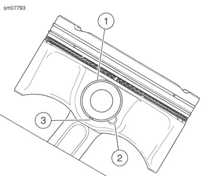
Figure 4-26. Piston Circlip: 1. Circlip; 2. Cut-out; 3. End gap
Disassemble
1. See Figure 4-25. Remove piston rings.
- a. Remove compression ring (1).
- b. Remove tapered ring (2).
- c. Remove three-piece oil control ring (3).
Clean and inspect
1. Clean all parts thoroughly.
2. Clean piston.
- a. Clean piston head.
- b. Clean ring grooves.
- c. Clean piston body.
3. Inspect all parts for wear.
- a. Inspect piston for damage or wear. Replace as necessary.
- b. Measure piston pin diameter. Compare to specifications. Refer to Table 4-10.
Check piston ring gap
Notes:
- Always use new piston rings. Piston rings take a definite set and must not be reused if the engine has been operated. Always deglaze (or hone) the cylinder before installing new rings.
- Insufficient ring gap may cause the ends to abut at operating temperatures. This will result in ring breakage, cylinderscuffing and/or piston seizure.
- Excessive ring gap results in high oil consumption and blow-by of exhaust gases. Blow-by contaminates the oil supply and leaves sludge in the crankcase. It also reduces engine efficiency by weakening the combustion seal necessary for efficient transfer of energy to the piston.
- Ring end gap dimensions also apply to oversize rings. Replace ring if end gap exceeds specification. If end gap is under specification, filing is permissible.
1. See Figure 4-27. Check ring end gap of each ring before installing piston.
- a. Insert piston upside down into top of cylinder and apply even downward force to align piston.
- b. Measure the ring end gap with a feeler gauge. Refer to Table 4-9 for specifications.
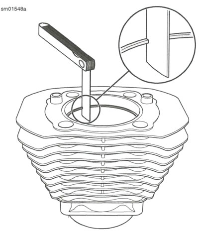
Figure 4-27. Check Piston Ring End Gap
Assemble
1. See Figure 4-28. Install three-piece oil control ring.
- a. Install lower side rail (5).
- b. Install spacer ring (4).
- c. Install upper side rail (3).
Note: Verify that the TOP markings on the taper and compression rings are aligned to the top of the piston.
2. Install tapered ring (2).
3. Install compression ring (1).
4. Verify that all piston rings rotate freely.
5. See Figure 4-29. Verify that all gaps are positioned as shown before installing piston.
- a. Rotate spacer ring so that the end gap (1) is aligned with piston pin hole (4).
- b. Rotate lower side rail so that the end gap (6) is 45 degrees right of the piston pin hole.
- c. Rotate upper side rail so that the end gap (2) is 45 degrees left of the piston pin hole.
- d. Rotate tapered ring so that the end gap (3) is 120 degrees left of the piston pin hole.
- e. Rotate compression ring so that the end gap (5) is 120 degrees right of the piston pin hole.
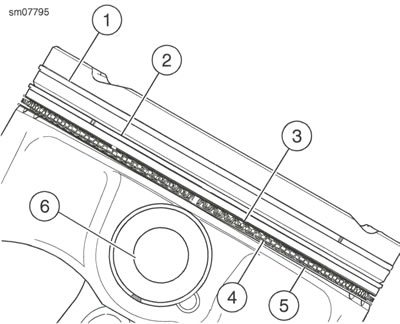
Figure 4-28. Piston Rings: 1. Compression ring; 2. Tapered ring; 3. Upper side rail; 4. Spacer ring; 5. Lower side rail; 6. Piston pin hole
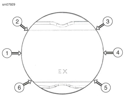
Figure 4-29. Piston Ring End Gaps: 1. Spacer ring end gap; 2. Upper side rail end gap; 3. Tapered ring end gap; 4. Piston pin hole; 5. Compression ring end gap; 6. Lower side rail end gap
Complete
1. Install cylinder. See Removing and installing cylinders.
2. Install chain guides. See Chain guide.
3. Install cylinder head. See Cylinder heads.
4. Install cam sprocket and timing chain. See Camshaft sprocket and timing chain.
5. Install alternator. See Removing and installing alternator.
6. Install crankshaft gear. See Crankshaft gear.
7. Install clutch cover. See Clutch cover.
8. Install cylinder head covers. See Cylinder head covers.
9. Install intake manifold. See Induction module.
10. Install breather hoses. See Breather hoses.
11. Install air cleaner assembly. See Air cleaner assembly.
12. Install exhaust system. See Exhaust system.
13. Secure rear of fuel tank. See Lift rear of fuel tank.
14. Connect negative battery cable. See Power disconnect.
15. Install front belt guard. See Belt guards.