Remove left cover. See Group 46.
Drain engine oil. See Group 00.
Place motorcycle on side stand.
Position a drip tray beneath the engine.
Remove drain plug (1) from water pump.
Hold a funnel below the drain and open the radiator cap.
Drain off all the coolant.
Place motorcycle on its centre stand.
Remove the gear shift pedal.
Remove the starter motor. See Group 12.
Disconnect clutch cable at release shaft.
Disconnect the oil return line from the engine and the oil tank.
Disconnect the oil line from the cylinder head.

Using hose clip pliers, BMW No. 17 5 500, remove hose clips (1).
Remove left engine housing cover.
Removing pressure plate
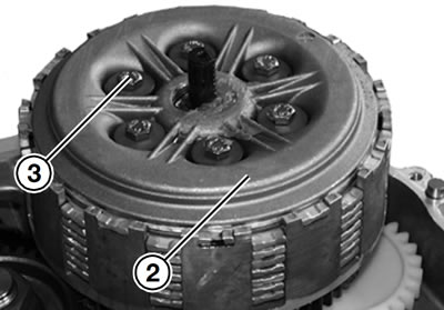
Remove hex screws (3) in diagonally opposite sequence.
Lift off complete pressure plate (2).
Check length of compression springs.
Disassembling and reassembling pressure plate
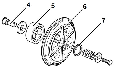
Remove circlip (7) with circlip pliers.
Check splines on release head (4).
Heat pressure plate (6) to 80°C (176°F) and drive in grooved ball bearing (5), using a suitable drift (such as a socket, for example).
Note: Use temperature measuring device, BMW No. 00 1 900, to check the temperature.
Grooved ball bearing (5) must turn easily.
Installation is the reverse of the removal procedure.
Removing clutch plates, driver and clutch cage
Note: When dismantling the clutch plate cluster, mark the order in which the plates are installed.
Take the plate cluster, lined plates (1) and inner plates (2) out of the clutch cage.
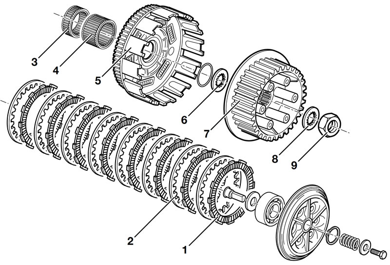
Using locating ring, BMW No. 21 4 600, secure clutch cage (5) and driver (7) in position.

Remove lock washer (8).
Note: Hex nut (9) is secured with Loctite 243 and should be heated if necessary before unscrewing.
Unscrew hex nut (9).
Remove driver (7).
Remove clutch cage (5) incl. serrated washer (6).
Remove needle cages (3, 4).
Installing clutch cage
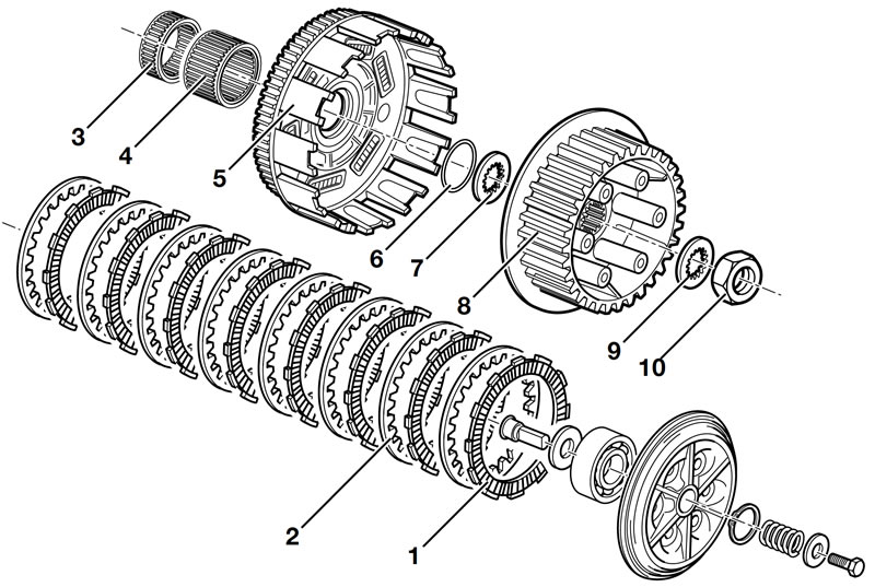
Coat needle sleeves (3, 4) with oil and install, with the small sleeve (3) down.
Insert O-ring (6) into groove under splines.
Install clutch cage (5); gears must all be in mesh.
Attach thrust washer (7) and press it against the O-ring until it is firmly seated and does not spring back.
Installing driver
Insert driver (8) and coat internal splines with Optimoly MP 3.
Fit serrated washer (9); it must engage securely.
Clean threads of compensating shaft and hexagon nut (10), coat threads with Loctite 243 and install nut.
Insert locating ring, BMW No. 21 4 600.
Tighten hex nut and tilt up retaining plate (8).
Tightening torques:
- Driver to compensating shaft (clean thread + Loctite 243): 140 Nm
Installing pressure plate
Insert the plates, starting with a steel plate. Install steel plates (2) and lined plates (1) alternately; with marked lined plate always at the top.
Note: Insert the topmost plate in the offset groove of the clutch cage.
Check clutch plates for wear
Measure the height of the 8 lined plates when pressed together.
Height of complete compressed plate cluster.
- Height of lined plate cluster: min. 27.5 mm (1.08 in)
- Height of complete plate cluster: min. 39.1 mm (1.54 in)
- Lined plate distortion: 0.25 mm (0.010 in)
- Steel plate distortion: 0.15 mm (0.006 in)
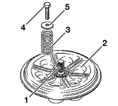
Install pressure plate (2).
Note: All springs (3) must be renewed after each clutch repair.
Install springs (3).
Uniformly tighten screws (4) with washers (5) in diagonally opposite sequence.
Position thrust head (1) correctly in relation to the release shaft and hold temporarily in position with grease.
Tightening torques:
- Pressure plate to driver: 10 Nm
Removing and installing releaser shaft
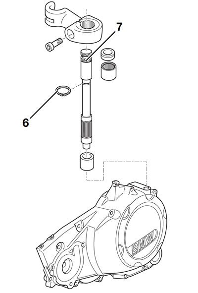
Remove keeper (6) for release shaft (7).
Withdraw release shaft from cover.
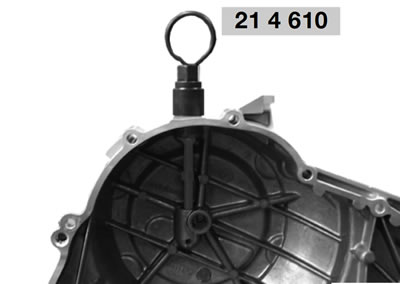
Using puller, BMW No. 21 4 610, pull out both needle roller bearings and the sealing ring together.
Installation is the reverse of the removal procedure: pay particular attention to the following.
Drive the lower and upper needle roller bearings in together with drift, BMW No. 21 4 640.
Insert release shaft.
Cover the splines on the release shaft with slide-on sleeve, BMW No. 21 4 620.
Using drift, BMW No. 21 4 630, drive in sealing ring.
