Prepare
1. Disconnect negative battery cable. See Power disconnect.
2. Drain engine oil. See Replace engine oil and filter.
3. Remove exhaust. See Exhaust system.
4. Remove right footrest and rear brake pedal assembly. See Rider foot controls.
5. Remove clutch cover. See Clutch cover.
Remove
| PART NUMBER | TOOL NAME |
| HD-51281 | CRANKSHAFT LOCKING TOOL |
| HD-51505 | CLUTCH LOCKING TOOL |
1. See Figure 5-11. Remove lifter plate.
- a. Remove screws (1).
- b. Remove lifter plate (2).
2. Install CRANKSHAFT LOCKING TOOL (Part No. HD-51281).
3. Install CLUTCH LOCKING TOOL (Part No. HD-51505).
4. Remove clutch.
- a. Remove nut (3).
- b. Remove cup washer (4).
- c. Remove clutch (5).
5. Remove thrust washer (6).
Install
| PART NUMBER | TOOL NAME |
| HD-51281 | CRANKSHAFT LOCKING TOOL |
| HD-51505 | CLUTCH LOCKING TOOL |
| FASTENER | TORQUE VALUE | |
| Clutch assembly nut | 160.0-170.0 Nm | 118-125 ft·lbs |
| Clutch lifter plate screws | 8.0-10.0 Nm | 71-88 in·lbs |
1. See Figure 5-11. Install thrust washer (6) with beveled side toward engine.
2. Install CRANKSHAFT LOCKING TOOL (Part No. HD-51281).
3. Install CLUTCH LOCKING TOOL (Part No. HD-51505).
4. Install clutch (5).
- a. Install clutch (5).
- b. Install cup washer (4) with concave side facing clutch.
- c. Install nut (3). Tighten to 160.0-170.0 Nm (118-125 ft·lbs).
5. Install lifter plate (2).
- a. Install lifter plate (2).
- b. Install screws (1). Tighten to 8.0-10.0 Nm (71-88 in·lbs)
6. Remove CRANKSHAFT LOCKING TOOL (Part No. HD-51281).
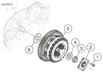
Figure 5-11. Clutch Assembly: 1. Screw (4); 2. Lifter plate; 3. Nut; 4. Cup washer; 5. Clutch; 6. Thrust washer
Disassemble
1. See Figure 5-12. Remove pressure plate and hub assembly.
- a. Remove clutch hub (13).
- b. Remove damper spring (11) and damper spring seat (12).
- c. Remove narrow friction plate (10).
- d. Remove steel plates (8) and friction plates (9).
- e. Remove inner friction plate (7).
- f. Remove pressure plate (6).
2. Remove washer (5).
3. Remove collar (4).
4. Remove oil pump gear (1).
5. Remove bearing (2).
Clean and inspect
Warning: Compressed air can pierce the skin and flying debris from compressed air could cause serious eye injury. Wear safety glasses when working with compressed air. Never use your hand to check for air leaks or to determine air flow rates.
1. Wash parts, except friction plates and bearing, in cleaning solvent. Dry parts with low-pressure, compressed air.
Note: If any individual plate shows evidence of wear or damage, replace all friction plates.
2. Check friction plates:
- a. Use low-pressure, compressed air to remove all lubricant. Do not dry with cloth.
- b. Look for worn or damaged fiber surface material on both sides.
- c. Measure thickness of each plate with a dial caliper or micrometer.
- d. Discard all friction plates if any one plate is less than 3.62 mm (0.142 in) thick.
Note: Discard any steel plate that is grooved or bluish in color. Blue plates are likely warped or distorted.
3. Check steel plates:
- a. Lay each plate on a precision flat surface.
- b. Insert feeler gauge between plate and flat surface in several places.
- c. Replace any steel plate that is warped more than 0.15 mm (0.006 in).
4. Check clutch hub:
- a. Check for excessive wear. Replace hub if worn or damaged.
5. Check bearings:
- a. Check bearings for smoothness. Replace bearing if it rotates roughly, binds or has any end play.
- b. Check ramps for excessive wear. Replace hub if ramps are worn or damaged.
Assemble
Note: If installing new friction plates, soak them for 10 minutes in GENUINE HARLEY-DAVIDSON H-D 360 20W50 MOTORCYCLE OIL and assemble while wet.
1. See Figure 5-12. Install bearing (2), if removed, using a suitable press.
2. Install oil pump gear (1).
3. Install collar (4).
4. Install washer (5).
5. Assemble pressure plate and hub assembly.
- a. See Figure 5-13. Install damper spring seat (3) and damper spring (12) on clutch hub (13).
Notes: Figure 5-14. The inner friction plate (1) has more oil grooves cut into the friction material than the other friction discs (2).
The narrow friction plate (3) is thinner than the other friction plates to accommodate the damper spring and seat.
- b. See Figure 5-12. Install narrow friction plate (10).
- c. Install steel plates (8) and friction plates (9).
- d. Install inner friction plate (7).
- e. Install pressure plate (6).
6. See Figure 5-15. Install pressure plate and hub assembly into clutch basket. Align friction plate tabs as shown.
- a. Align tabs of inner friction plate and friction plates (1) as shown.
- b. Align tabs of narrow friction plate (2) as shown.
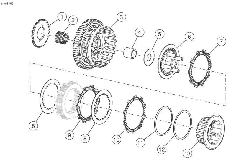
Figure 5-12. Clutch Assembly: 1. Oil pump gear; 2. Bearing; 3. Clutch basket; 4. Collar; 5. Washer; 6. Pressure plate; 7. Inner friction plate; 8. Steel plate (7); 9. Friction plate (6); 10. Narrow friction plate; 11. Damper spring; 12. Damper seat; 13. Clutch hub
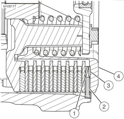
Figure 5-13. Damper Spring and Seat: 1. Damper spring; 2. Narrow friction plate; 3. Damper spring seat; 4. Clutch hub
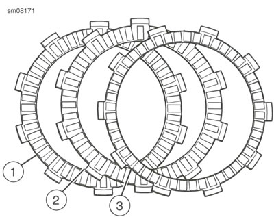
Figure 5-14. Friction Plates: 1. Inner friction plate; 2. Friction plate; 3. Narrow friction plate
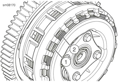
Figure 5-15. Friction Plate Tab Locations: 1. Friction plate tab; 2. Narrow friction plate tab
Complete
1. Fill with engine oil. See Replace engine oil and filter.
2. Install right footrest and rear brake pedal assembly. See Rider foot controls.
3. Install exhaust. See Exhaust system.
4. Install clutch cover. See Clutch cover.
5. Connect negative battery cable. See Power disconnect.
