Removing, disassembling/assembling water pump
Removing the oil/water pump
- Disconnect oil pressure warning and water pump temperature sensor wires from switches.
- Withdraw wires through hole in pump housing.
- Remove pump housing cover (1) and loosen the gasket by tapping lightly with a plastic-headed hammer.
- Remove the housing and loosen the gasket by tapping lightly with plastic-headed hammer.
- Remove oil-pump gear (7).
Disassembling the oil/water pump
- Clamp the pump housing by the sealing faces in a vice fitted with jaw protectors.
- Remove water pump impeller (2), holding pump shaft (6) to prevent it from turning.
- Remove water-pump impeller (2) with spacer bushing (3).
- Press out pump shaft (6).
- Examine the pump housing for damage.
Removing slipring seal and shaft sealing ring
- Drive out piston-ring-type oil seal (4) with drift, BMW No. 116721.
- Press out shaft sealing ring (5) with drift, BMW No. 116721.
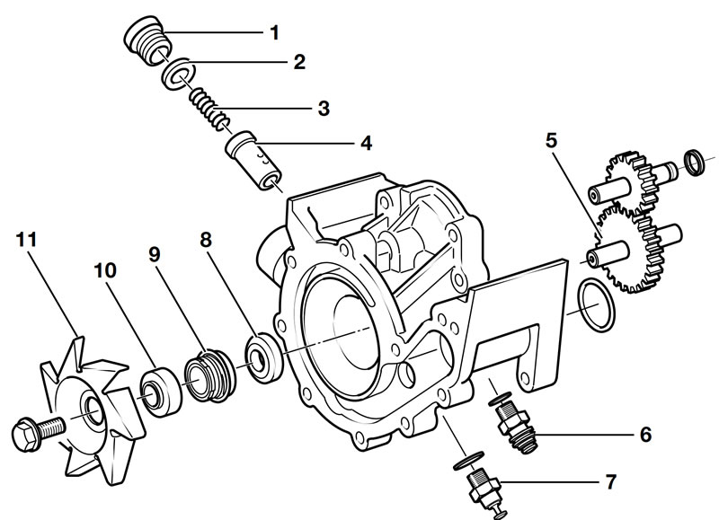
Removing the oil pressure relief valve
- Unscrew plug (1) and take out spring (3).
- Pull valve piston (4) out with a magnet and examine it for damage.
Installing the oil pressure relief valve
- Oil valve piston (4) lightly and install.
- Install spring (3) and tighten screw plug (1), fitted with new sealing ring (2).
Tightening torque:
- Oil pressure relief valve screw plug — 35 Nm
Oil-pressure switch, temperature sensor for water pump
Tightening torque:
- Oil-pressure switch (6) — 35 Nm
- Temperature sensor for water pump (7) — 9 Nm
Installing the pump shaft with shaft sealing ring and slipring seal.
Note: Clean the sealing ring seats.
- Insert pump shaft (5) (lightly oiled) into the housing.
- Place sliding sleeve, BMW No. 11 6 722, on pump shaft.
- Insert shaft sealing ring (8) into the guide sleeve of pressing-in tool, BMW No. 11 6 723, and press in with the open side facing inwards.
- Remove the sliding sleeve.
- Press in slipring seal (9) (free of grease) with pressing-in tool, BMW No. 11 6 724.
Installing water pump impeller
- Install water pump impeller (11) with spacing bushing (10). When tightening, hold the pump shaft to prevent it from turning.
Tightening torque:
- Water pump impeller — 33 Nm
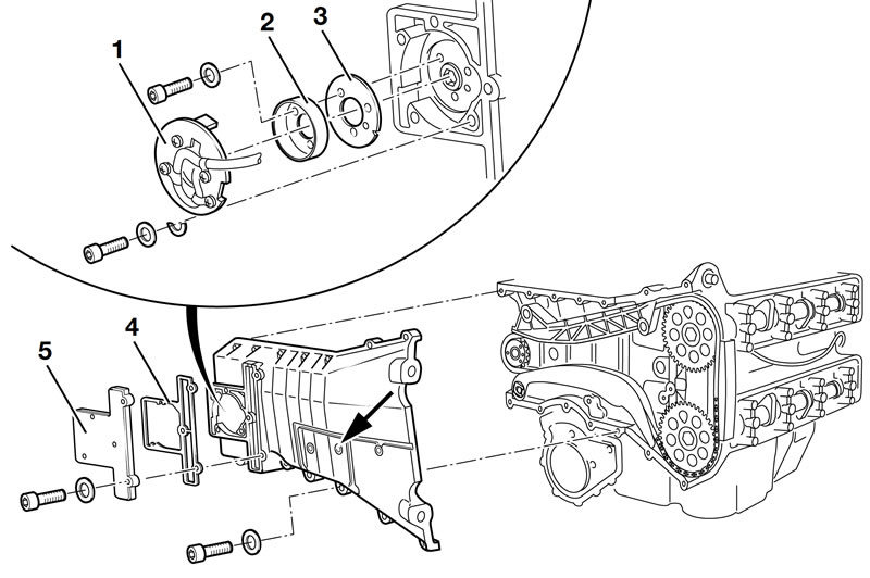
Removing timing chain cover
Removing cylinder head cover
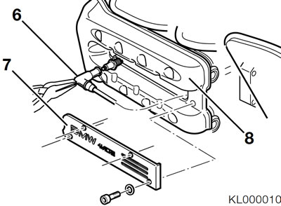
- Remove heat shield (7).
- Pull off spark plug caps (6) with flat pliers.
- Remove cylinder head cover (8).
Removing ignition pulse generator
- Remove cover (5).
- Remove gasket (4).
Note: Mark the position of the magnetic gate in relation to the engine block, or remove it in the top dead centre (TDC) position.
- Remove magnetic gate (1), noting the presence of semi-circular shims.
- Remove rotor (2) and take off adjusting disc (3).
Removing timing chain cover
- Remove the screw plug (arrow) for the pin in the timing case cover.
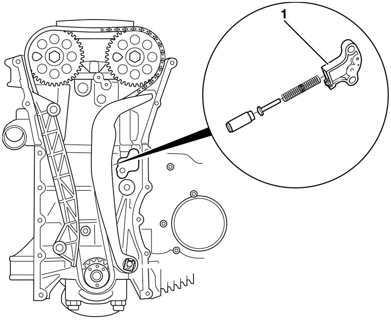
- Use pin, BMW No. 11 6 740, to prevent chain tensioner (1) moving.
Note: Turn the camshaft in its normal direction of rotation until oil is forced out of the chain tensioner and the pin can be inserted all the way.
- Disconnect oil pressure switch and water pump temperature switch cables. Pull the cables out through the cable duct in the timing case cover.
- Remove the screws, loosen the timing case cover with light blows of a plastic-faced hammer and remove.
- Slacken the chain tensioner and remove it from the timing case cover.
Removing/installing sealing ring in timing case cover
- Using a drift, drive the sealing ring inwards to remove.
Note: Remove traces of paint and clean the seat of the sealing ring.
- Press the sealing ring in from the inside using pressing-in tool, BMW No. 11 1 610, and handle, BMW No. 0 05 500.
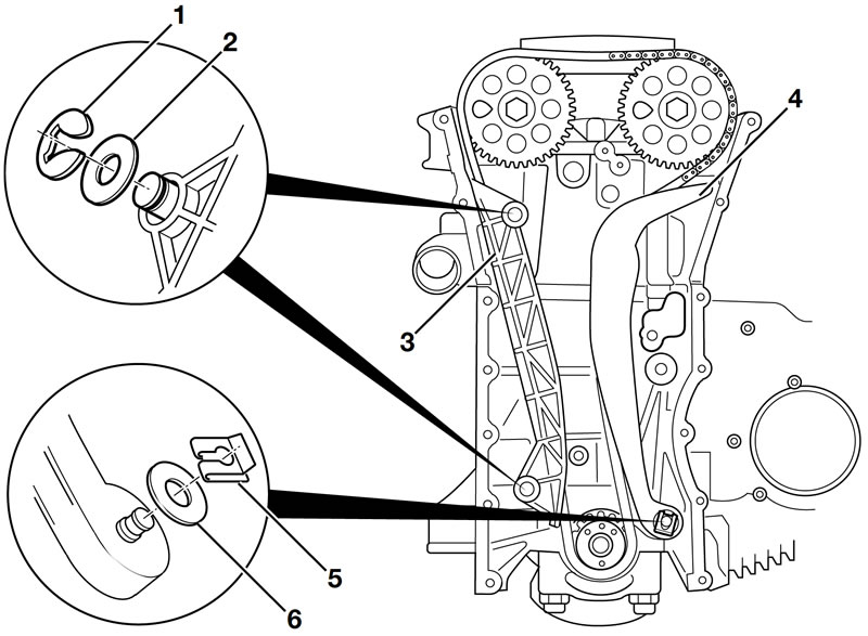
Removing the timing chain
Caution: Centre the piston in the cylinder (cylinder 1 approx. 90° before top dead centre), to avoid damage to the valves and piston. Turn the crankshaft in the counter-clockwise direction only.
Removing camshaft chain sprockets
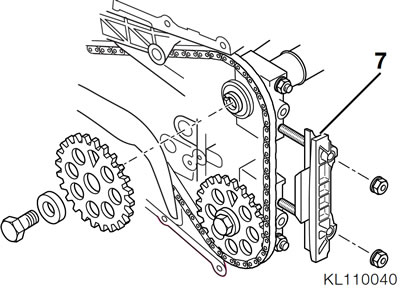
- Slacken the nuts securing the slide rail (7).
- Remove the screws securing the chain sprok-kets, holding the camshaft at the hexagon.
- Remove the chain sprockets and slide rail.
Removing chain tensioner rail
- Remove the keeper (5) and washer (6).
- Remove tensioner rail (4).
Removing chain guide rail
- Remove snap rings (1) and washers (2) from locating pins.
- Remove guide rail (3) with bushing and timing chain.
Renewing tensioning strap for chain tensioner rail
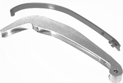
- Unclip the tensioning strap from the tensioner rail.
Removing, disassembling and assembling cylinder head
Removing camshafts
- Turn the camshafts until the tips of the cams are clear.
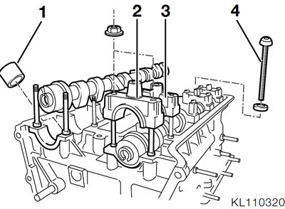
- Remove the bearing caps (2) for the thrust bearings first, to prevent tilting.
- Uniformly release the screws securing the radial bearing caps (3) and remove the bearing caps.
- Remove the camshafts.
Removing bucket-type tappets
Note: Make a note of which bucket-type tappets belong to which valves.
- Use the rubber suction device, BMW No. 11 3 251, to pull the bucket-type tappets (1) out of the cylinder head.
Removing cylinder head
- Remove the spark plugs and ignition cables.
See Group 12.
Note: Place a drip tray in position underneath the engine to catch escaping coolant.
- Release the cylinder head screws (4) using Torx socket T 50, BMW No. 00 2 630.
- Remove the cylinder head, tapping the gasket lightly with a plastic-headed hammer to release, if necessary.
Removing valves
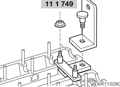
- Install support plate, BMW No. 11 1 749, for the valve spring compressor at the rear of the cylinder head (not the timing end).
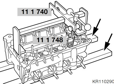
- Install the valve spring compressor, BMW No. 11 1 740.
- Use compressor cage, BMW No. 11 1 748.
Caution: Centre the compressor cage in order to avoid damaging the tappet bores.
- Place the cylinder head on suitable blocks (arrows) to ensure adequate clearance for valve removal.
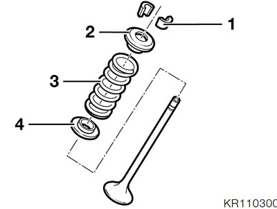
- Tap the valve collets (1) lightly to release.
- Compress the valve spring (3) using compressor cage, BMW No. 111748.
- Remove valve collets (1) with a magnetised screwdriver.
- Release valve spring (3) and remove upper spring retainer (2), valve spring and lower spring retainer (4).
- Remove the valve stem seal with special pliers, BMW No. 11 1 250.
Machining valve seat
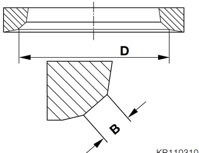
D = valve diameter; B = valve seat width
- Machine the valve seat with turning tool, BMW No. 003530.
- When remachining, the correct width of the valve seat must always be maintained.
Note: If valve seat has been machined, install and grind in new valve.
Installing valve and valve stem seal
Note: If a valve is removed, the valve stem seal must be renewed.
- Oil the stem when installing the valve.
- Insert the lower spring retainer.
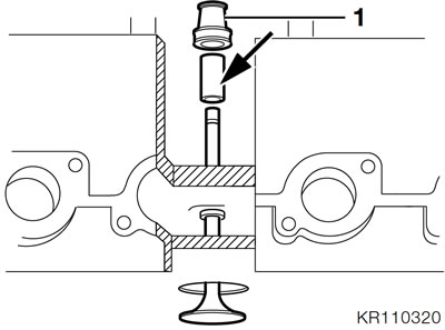
- Place a shrink-fit tube approx. 20 mm (0.79 in) long on the valve stem and heat it up.
- Drive in valve stem seal (1) with the assembly tool, BMW No. 11 5 602, until resistance is felt.
Caution: Remove the shrink-fit sleeve from the valve stem.
- Install the valve spring.
- Install the upper spring retainer.
Caution: Centre the compressor cage in order to avoid damaging the tappet bores.
- Compress the valve spring, lightly oil the valve collets and insert them, then release the spring.
- Clean and oil the bucket-type tappet and install.
Removing/installing crankshaft gear and rotor flange
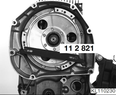
- Mount the retaining device, BMW No. 11 2 821, on the clutch housing as shown.
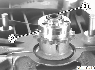
- Release the screw (3) securing the crankshaft gear and rotor flange.
- Remove the rotor flange (2), tapping it lightly to release if necessary, and remove the gear.
- Installation is the reverse of the removal procedure.
Tightening torque:
- Rotor flange — 50 Nm
Removing crankshaft
Note: Remove the driver first if the intermediate flange is to be removed after the crankshaft.
Removing big end bearings
- Bring pistons 1 and 4 to BDC position.
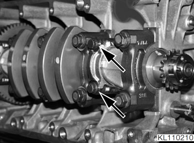
- Release the connecting rod screws (arrows).
- Carefully release and remove the big-end bearing caps.
Caution: Make a note of which caps belong to which connecting rods, and note the installed positions.
- Repeat the work sequence at cylinders 2 and 3.
Removing main bearings (engine installed)
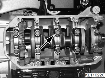
- Loosen all but one (arrow) of the main bearing bolts.
Note: Make a note of which caps belong to which main bearings, and note the installed positions. Bearing caps 1 - 3 are marked for identification. Bearing 4 (thrust bearing) and bearing 5 are not marked. Cylinder 1 = timing end of engine.
- Remove the bearing caps.
- Remove the final bolt.
- Take off the bearing cap, pressing the crankshaft in towards the housing while doing so.
Removing main bearings (engine removed)
- Remove all main bearing bolts and remove the bearing caps and the crankshaft.
Removing, disassembling and assembling piston with conrod
Removing piston with conrod
Note: Make a note of which pistons belong to which cylinders, and note the installed positions.
- Working from the crankshaft side, press the piston with conrod out of the cylinder.
Disassembling piston
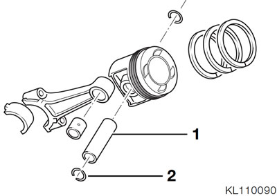
- Remove the wire circlip (2) at one side.
- Press out piston pin (1) with drift, BMW No. 116710.
- Carefully remove piston rings with piston ring pliers.
Note: Note the installed position.
- Clean the piston.
Checking piston dimensions
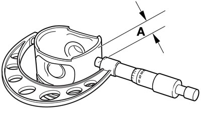
- Use caliper gauge to measure the piston diameter at planes "A".
Dimension "A" — 10 mm (0.4 in)
- Measure piston ring edge clearances with feeler gauge.
- Measure the end gaps of the piston rings in the cylinder.
- For correct edge clearances and end gaps, see Technical Data.
Assembling pistons
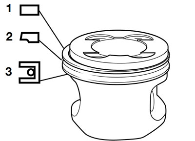
Install piston rings, using piston-ring pliers.
Note: The "Top" inscription is uppermost and according to the installed position previously noted.
- 1st groove: Rectangular-section ring.
- 2nd groove: Taper-face oil-control ring; note pin for butt joint.
- 3rd groove: U-Flex ring with spring.
Note: The gap in the spring must be offset by 180° in relation to the Flex ring gap.
Checking cylinder dimensions
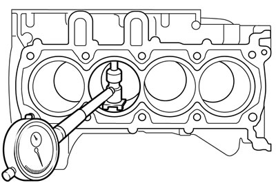
- Measure cylinder bores with inside-diameter measuring gauge.
- Measure each cylinder bore at 3 levels, taking two measurements at right angles at each level: in the direction of forward travel and at a right angle to it.
Checking that conrod bores are parallel
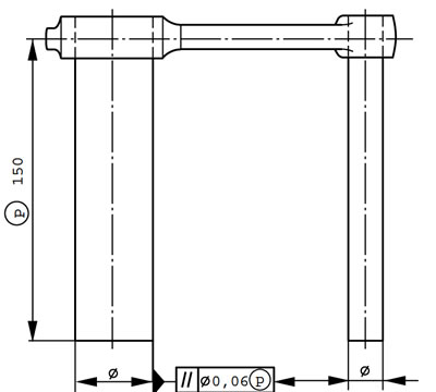
- The difference over the reference length "P" must not exceed 0.06 m (0.002 in).
Reference length "P" — 150 mm (5.9 in)
Assembling pistons and conrods
- Note weight tolerances when replacing conrods: use only conrods of the same weight class.
Weight tolerance±4 g (0.14 oz.)
- Weigh the conrods to determine the weight class.
Weight classes
| Class | Weight in g (oz.) | ||
| 0 | 413 | ...416.9 (14.578.. | 14.716) |
| 1 | 417 | ...420.9 (14.720.. | 14.857) |
| 2 | 421 | ...424.9 (14.861.. | 14.998) |
| 3 | 425 | ...428.9 (15.002.. | 15.140) |
| 4 | 429 | ...432.9 (15.143.. | 15.281) |
| 5 | 433 | ...436.9 (15.285.. | 15.422) |
| 6 | 437 | ...440.9 (15.426.. | 15.563) |
| 7 | 441 | ...444.9 (15.567.. | 15.704) |
Applying light pressure, push the piston pin through the small-end bushing.
Note: The oil bore in the small-end bore is at the top in the installed position. The arrow on the piston crown must point in the forward direction of travel.
Install only pistons of the same weight group.
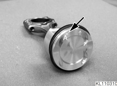
- Check the marks on the piston crowns (arrow) to determine the weight class.
Weight classes for pistons
| Weight of piston in g (oz.) | 189 ...195 (6.671...6.883) | 195 ...210 (6.883...7.413) |
| Marking | - | + |
Caution: Always use two new wire circlips per piston pin when reassembling.
- Assemble piston and conrod.
Measure backlash at the countershaft
Note: Abnormal noises, especially at low engine speeds, could be due to excessive backlash between the crankshaft/countershaft gearing.
Caution: Always measure backlash with the engine cold.
- Remove alternator.
See Group 12.
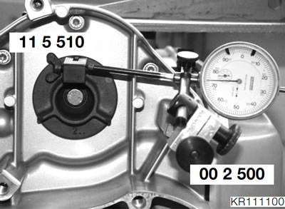
- Secure dial-guage holder, BMW No. 00 2 500, to gearbox intermediate flange.
- Use the clamping screw to secure the clamp, BMW No. 115 510, to the upright vane of the driver.
- Adjust the dial gauge, BMW No. 00 2 510, such that the needle touches the mark on the tool (3 mm/0.1 in from outside edge) on the reference face.
- Manually turn the driver and note dial-gauge reading.
- Remove the clamp, BMW No. 11 5 510.
- Turn the crankshaft to rotate the driver through 120°.
- Secure the clamp to the second driver vane and use the dial gauge to measure the backlash.
- Take a third measurement.
- Calculate the average over the three measured values.
- Replace the countershaft if the average obtained from the three measurements is at least 0.03 mm (0.001 in).
Determining countershaft
| Average of 3 measurements | Colour code | Stage |
| 0.03 mm ...0.06 mm (0.0012...0.0024 in) | green | - 0.040 mm (- 0.0016 in) |
| greater than 0.06 mm (0.0024 in) | yellow | - 0.080 mm (- 0.0031 in) |
Removing intermediate flange
- Remove the ignition coil.
See Group 12.
- Remove the clutch.
See Group 21.
Removing driver
Note: The driver can be removed only with the crankshaft installed.
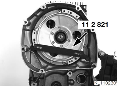
- Mount the retaining device, BMW No. 11 2 821, as shown (arrow).
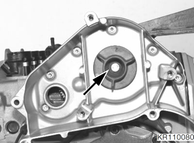
- Remove screw (arrow).
- Pull the driver off by hand.
- Use puller, BMW No. 00 8 400, if the driver is a tight fit on the shaft.
Removing clutch housing
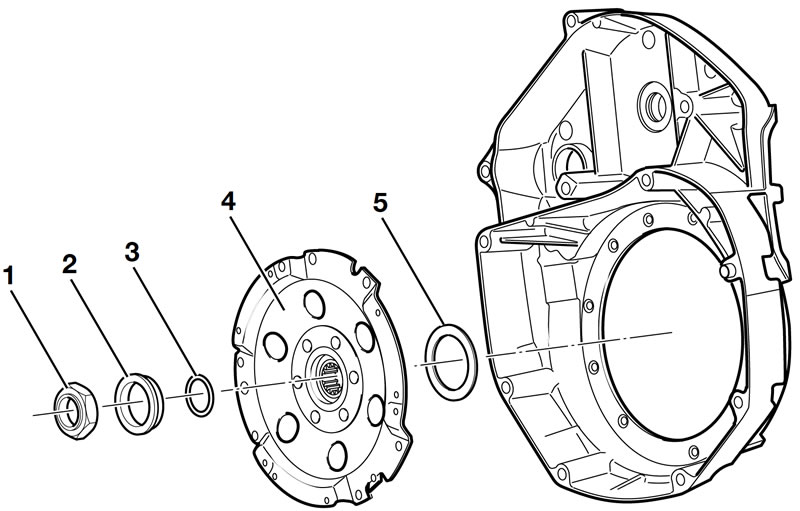
Caution: After unscrewing nut (1), do not strike the output shaft or turn the engine over, so that output shaft endplay cannot cause damage to the crankcase or pump housing.
Unscrew nut (1) and remove thrust ring (2).
Rock the clutch housing backwards and forwards until the O-ring (3) is accessible and remove the O-ring.
Caution: Do not lever the puller against the stub shaft.
Pull off clutch housing (4), noting the presence of thrust washer (5).
Removing intermediate flange
- Use Torx socket T 30, BMW No. 0 02 600, to release the screws.
- Remove the intermediate flange and loosen the gasket by tapping lightly with plastic-headed hammer.
Disassembling/assembling intermediate flange
Removing the driver bearing
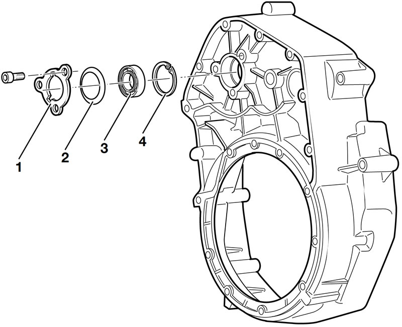
- Remove thrust plate (1).
- Remove cup spring (2).
- Remove ball bearing (3) with puller, BMW No. 0 08 570, and internal puller 21/3, BMW No. 008574.
- Remove retaining ring (4).
Installing driver bearing
- Install retaining ring (4).
Note: Use temperature measuring device, BMW No.001 900, to check heat rise.
- Heat the intermediate flange at the bearing seat to approx. 120°C (248°F).
- Press the ball bearing into the bore until seated against retaining ring.
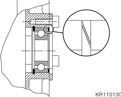
- Insert the cup spring with the larger diameter facing the bearing.
- Install the thrust plate with the large cutout at the top.
Tightening torque:
- Thrust plate (clean thread + Loctite 243) — 9 Nm
Removing/installing shaft sealing ring for driver
- If the intermediate flange has been removed, lever out the sealing ring.
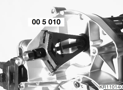
- If the intermediate flange is installed, use puller, BMW No. 005010, to remove the sealing ring.
Note: Clean the sealing ring seat.
- Pre-shape the sealing ring with the thumbs and drive it in (in a dry condition) with a drift, BMW No. 11 1 620, and handle, BMW No. 005500.
Removing countershaft and layshaft with freewheel
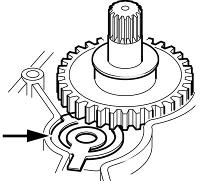
- Pull the countershaft and layshaft out of the crankcase together.
- Note special spring (arrow).
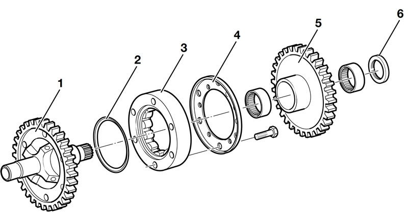
Disassembling/assembling freewheel
Disassembling freewheel
- Pull washer (6) and freewheel gear (5) off the layshaft (1).
- Clamp the layshaft into a vice with soft jaws (smooth side down).
- Remove cover plate (4).
- Pull off freewheel cage (3).
- Take out cup spring (2).
- Press out the needle bearing.
Assembling freewheel
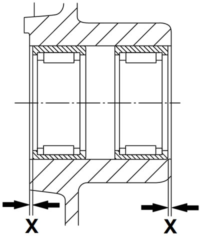
- The inscription on the needle roller bearing faces down.
- Press the needle bearings into the freewheel gear, making sure that distance (X) from edge is uniform.
Distance "X" — 0.2...0.6 mm (0.007...0.023 in)
- Install the cup spring with the larger diameter facing the layshaft.
- Insert the freewheel (oiled with engine oil) into the outer race.
- Position the outer race with freewheel on the lay-shaft (sprag toward cover plate); the cup spring must engage the outer race.
- Install the cover plate.
Tightening torque:
Cover plate — 10 Nm
- Push the freewheel gear on to the layshaft while turning it clockwise.
- Push the thrust washer on to the layshaft.
Removing/installing needle bearing for layshaft and shaft sealing ring in crankcase
Removing bearing
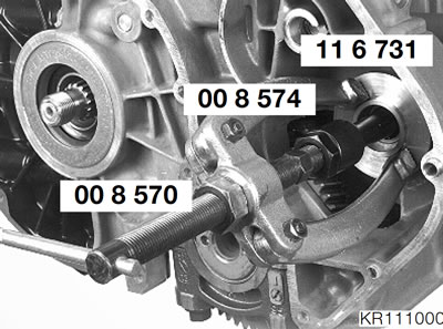
- Place support ring, BMW No. 11 6 731, in position and remove bearing with puller, BMW No. 008570, and internal puller 21/3, BMW No. 008574.
- If a defective bearing cannot be pulled out, carefully cut through the needle roller race (with a grinder).
Removing shaft sealing ring
- Lever out the shaft sealing ring.
Installing shaft sealing ring
- Clean the sealing ring seat.
- Drive in the new shaft sealing ring with a drift, BMW No. 116732.
Installing bearing
- The inscription on the needle roller bearing faces outwards.
- Drive the bearing in with a drift, BMW No. 116733.
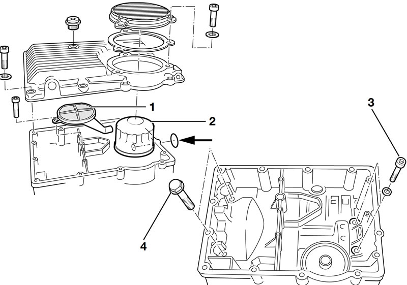
Removing output shaft
Removing oil sump
- Remove the screws.
- Loosen the gasket with light blows of a plasticfaced hammer and take off the oil sump.
Removing the oil mesh strainer and oil filter
- Remove the screw and pull off oil mesh strainer (1).
- Remove the O-ring for the oil mesh strainer (arrow) from the lower part of the crankcase.
- Unscrew oil filter (2) with the oil filter wrench, BMW No. 114650.
Removing lower part of crankcase
- Remove the screws securing the lower part of the crankcase.
- Remove screws (4) for the shouldered bearing and screws (3) for the needle roller bearing.
- Loosen the gasket with light blows of a plasticfaced hammer, and remove the lower part of the crankcase. Note the O-rings for the water and oil passages.
- Carefully lift out the output shaft; the needle roller bearing and circlip are loose on the shaft.
Removing/installing oil level sight glass
- Using a large screwdriver, pierce the plastic window and lever out the oil level sight glass.
Note: Clean the sealing face.
- Coat the outer circumference of the oil level sight glass with engine oil.
- Drive in the oil level sight glass with a drift, BMW No. 005550.
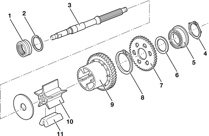
Disassembling/reassembling output shaft
Disassembling output shaft
- Remove needle roller race (1) and circlip (2).
- Remove output shaft (3) from the damper housing (9) and remove rubber dampers (11).
- Drive the output shaft out of the inner section of the damper (10) with a plastic-faced hammer.
Disassembling tensioning gear
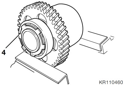
- Clamp the damper housing into a vice with soft jaws, to take the load off circlip (4).
- Remove circlip (4) with circlip pliers.
- Insert a puller, BMW No. 00 8 400, in the opposite cutouts of the gearwheel and pull ball bearing (5) off with pressure block, BMW No. 331307.
- Remove spacing ring (6), turn tensioning gearwheel (7) clockwise with counter-holder, BMW No. 124600, and pull upwards.
- Remove tensioning spring (8).
Note: Inspect all parts for damage or wear.
Assembling tensioning gear
- Insert the tensioning spring.
- Engage the tensioning spring on the pin in the tensioning gear and turn it clockwise with the counter-holder, BMW No. 124600, until the pin of the tensioning gear engages the hole in the gear.
- Clamp the tensioning gear with damper housing in a vice with soft jaws.
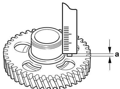
- Measure distance "a" from the base of the ball bearing seat to the tensioning gear.
Caution: The thickness of the spacing washer must never exceed this measurement.
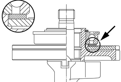
- Place a suitable spacing washer (arrow) on the tensioning gear.
Note: Use temperature measuring device, BMW No. 00 1 900, to check heat rise.
- Heat the ball bearing to approx. 80°C (176°F) and place it in position (with shoulder uppermost).
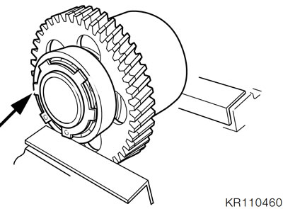
- Clamp the damper housing and the ball bearing together in the vice (with soft jaws).
- Using circlip pliers, insert the snap ring (arrow) into the groove in front of the bearing.
- The circlip must snap completely into the groove.
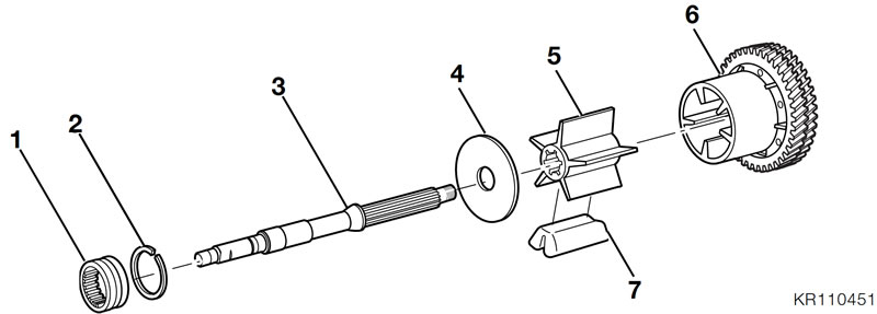
Assembling damper
- Insert the rubber dampers (7) into the damper housing (6).
Note: New parts must be oiled lightly.
- Push the retaining plate (4) onto the output shaft (3), slightly heat the inner part of the damper (5) and press it into position on the shaft.
- Push the damper housing on to the output shaft.
