Installing output shaft
- Push the snap ring (2) and the needle roller race (1) onto the output shaft.
- Place the output shaft in the crankcase.
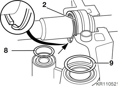
Note: Make sure that the open end of the snap ring (arrow) is facing downward in the crankcase.
- Install O-rings (8, 9) for the water and oil passages.
Assembling the crankcase
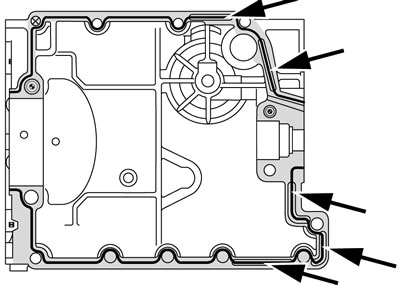
- Check that sealing face is clean and degreased and apply a thin coat of Omni VISC 1002, see black line on sealing face with grey shading.
- Fill the expansion grooves (arrows) with sealing compound.
Note: Remove excess sealant with a spatula.
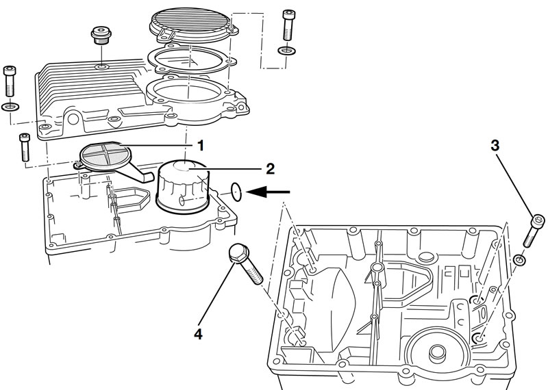
- Mate the two halves of the housing.
- Insert screws (4) for shouldered bearing and screws (3) for needle roller bearing, and tighten alternately.
- Tighten the screws for the lower part of the crankcase.
Tightening torque:
- Shouldered bearing — 40 Nm
- Needle roller bearing — 20 Nm
- Lower part of crankcase — 10 Nm
Installing oil mesh strainer
- Install a new O-ring (arrow) and place oil mesh strainer (1) in position.
Installing oil filter
- Coat the oil filter sealing ring with oil.
- Install the oil filter (2), using oil-filter wrench, BMW No. 114650.
Tightening torque:
- Oil mesh strainer — 10 Nm
- Oil filter — 11 Nm
Installing oil sump
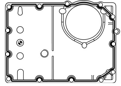
- Check that sealing face is clean and degreased and apply a thin coat of Omni VISC 1002, see black line on sealing face with grey shading.
- Install oil sump and cover for oil filter, if necessary.
Tightening torque:
- Oil sump — 10 Nm
- Oil filter cover — 10 Nm
- Oil drain plug — 30 Nm
Installing intermediate flange
Installing freewheel
- Oil the needle roller bearing well.
- Insert the freewheel into the crankcase helicalcut gear first.
Installing countershaft
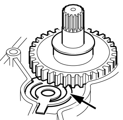
Caution: Insert the spring so that the large external diameter (arrow) projects upwards and is pre-loaded against the freewheel gear.
- Insert the countershaft into the crankcase with the small gearwheel facing down.
Installing intermediate flange
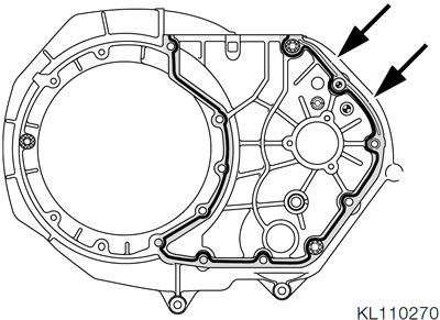
- Check that sealing face is clean and degreased and apply a thin coat of Omni VISC 1002, see black line on sealing face with grey shading.
- Fill the expansion groove (arrow) with sealing compound.
Note: Remove excess sealing compound with a spatula.
- Install the intermediate flange (with locating sleeves).
- Use Torx socket T 30, BMW No. 00 2 600, to tighten the screws.
Tightening torque:
- Intermediate flange — 9 Nm
Installing output shaft sealing ring
Note: Clean the sealing ring seat. Oil the sealing ring and, with the aid of a guide, slip it onto the drift.
- Drive in shaft sealing ring with drift, BMW No. 111630, and handle, BMW No. 005500.
Installing clutch housing
- Oil the internal splines of the clutch housing.
- Place thrust washer in position between output shaft and intermediate flange; if necessary use a blob of grease to hold the thrust washer in position.
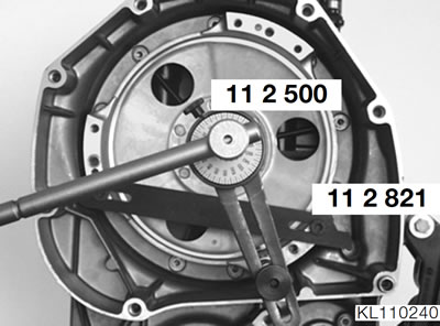
- Manoeuvre the clutch housing into position.
- Mount the retaining device, BMW No. 11 2 821, on the clutch housing in the position shown.
Caution: Secure with new nuts. Always use a new O-ring.
- Place O-ring and thrust ring in position.
- Install the nut with the collar to the outside and tighten to specified torque (140 Nm), the damper is compressed.
- Slacken and then retighten the nut (50 Nm).
- Use angle-of-rotation gauge, BMW No. 11 2 500, to tighten the nut fully.
Tightening torque:
- 1. Clutch housing nut — 140 Nm
- 2. Slacken off
- 3. Retighten to — 50 Nm
- 4. Wrench angle — 60°
Installing driver
Note: The driver can be installed only with the crankshaft installed.
- Push driver on to layshaft.
- Tighten the securing screws.
Tightening torque:
Driver — 50 Nm
- Remove the retaining fixture, BMW No. 112821.
- Install the clutch.
See Group 21.
Installing crankshaft
- Clean and lightly oil the bearing journals of the crankshaft.
Note: Bearing caps 1-3 are marked for identification; bearing 4 (thrust bearing) and bearing 5 are not marked.
- Place the crankshaft in position in the crankcase and position the bearing caps in their grooves.
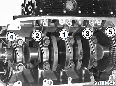
- Tighten the bearings in the order shown, starting from the centre and working outwards.
Tightening torque:
- Main bearings — 50 Nm
Measuring crankshaft bearing play
Measuring radial play
- Turn the crankshaft to top dead centre at the bearing to be measured.
- Take off the bearing cap.
- Wipe off oil at the bearing journal and bearing shell.
- Measure bearing play with Plastigage, BMW No. 002590.
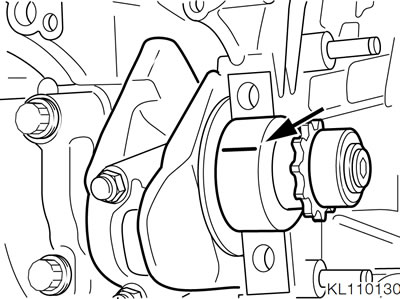
- Place the Plastigage strip (arrow) over the entire bearing width and 6 to 8 mm (0.2 to 0.3 in) off centre.
- Place the bearing cap in position and tighten the securing screws.
Tightening torque:
- Main bearings — 50 Nm
Note: Do not turn the crankshaft any more.
- Remove bearing cap.
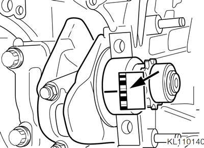
- Compare the width of the strip with the scale (arrow) in order to determine bearing play.
- Remove all traces of Plastigage from the shaft journal and bearing shell.
- Radial play — 0.020...0.056 mm (0.0007...0.0022 in).
- Wear limit — 0.130 mm (0.0051 in).
Measuring endplay
- Install the crankshaft.
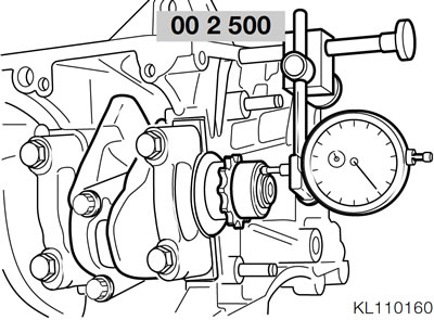
- Secure dial gauge holder, BMW No. 00 2 500, with dial gauge in tapped bore for timing case cover.
- Move the crankshaft backwards and forwards as far as it will go and take the dial gauge readings.
- Axial play — 0.080.0.173 mm (0.0031...0.0068 in).
- Wear limit — 0.250 mm (0.0098 in).
Installing piston with conrod
- Turn the crankpin in question to bottom dead centre.
- Make sure that the pistons are in the same weight category.
Caution: Note the pin for locating the end gap of the taperface oil-control ring in the 2nd groove.
Space the piston ring gaps at approx. 120° offsets.
Thoroughly oil the piston rings, piston skirt and cylinder wall.
Insert the piston into the sliding sleeve, BMW No. 116700.
The arrow on the piston crown must point towards the timing end of the engine (cylinder 1). Insert the piston with conrod into the cylinder until the sliding sleeve is touching the crankcase. Carefully push the piston by hand out of the sleeve and into the cylinder.
Installing big end bearing
Caution: Do not accidentally interchange conrods or bearing shells. Take great care to reinstall the bearing shells in their original positions.
Always use new big-end bearing screws.
- Turn the crankpin of the cylinder in question to bottom dead centre.
- Oil the crankpin and move the conrod into position.
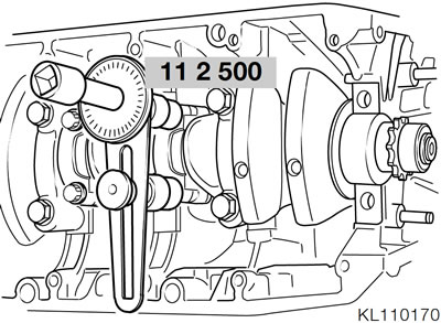
- Place the big-end bearing cap in position and tighten the securing screws to 20 Nm.
- Use angle-of-rotation gauge, BMW No. 11 2 500, to tighten the big-end bearing screws another 80°.
Tightening torque:
- Big end bearings — 20 Nm
- Wrench angle — 80°
Measuring big end bearing play
- Remove the screws and remove the bearing cap and clean the crankpin and bearing cap to remove oil.
- Measure bearing play with Plastigage, BMW No. 002590.
- Place the Plastigage strip (arrow) over the entire bearing width and 6 to 8 mm (0.2 to 0.3 in) away from the centre of the crankpin.
- Place the bearing cap in position and tighten the securing screws to 20 Nm.
Note: Do not turn the crankshaft any more.
- Use angle-of-rotation gauge, BMW No. 11 2 500, to tighten the big-end bearing screws another 80°.
Tightening torque:
- Big end bearings — 20 Nm
- Wrench angle — 80°
- Remove the screws and remove the bearing cap.
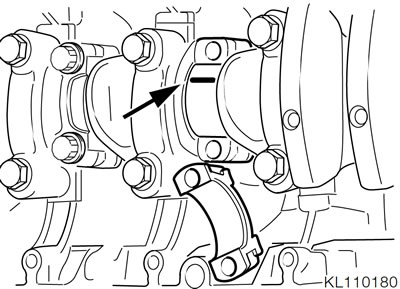
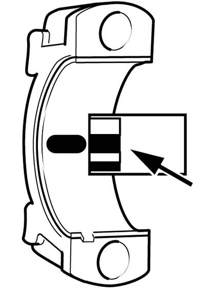
- Use the comparison scale (arrow) to determine bearing play.
- Bearing play 0.030...0.066 mm (0.0012...0.0026 in)
- Wear limit — 0.130 mm (0.0051 in)
Checking dimensions of crankshaft
- If measurement reveals that bearing clearance is excessive, the crankshaft must be measured.
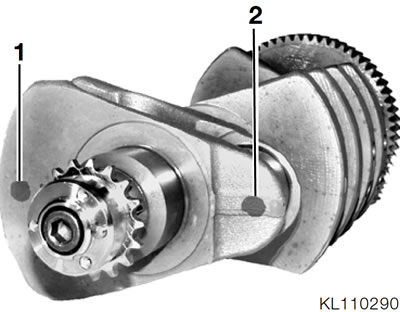
- The crankshaft can be ground to repair size "1"; the crankshaft is marked with the appropriate number of paint spots at the bearing journal.
Colour code at timing end of crankshaft:
- Grinding stage 1 at crankshaft bearing journal (1).
- Grinding stage 1 at crankpin (2).
- The absence of paint spots identifies the grinding stage as "0".
Note: Only a crankshaft marked as grinding stage "0" can be ground.
Crankshaft dimensions
See Technical Data.
- Grinding must be followed by heat treatment and finishing before the crankshaft is reinstalled.
- When renewing the bearing shells, make sure that the colour marks on the crankpins and big end bearings match.
Installing cylinder head
Note: Remove the bucket tappets before installing the cylinder head. Make a note of which bucket tappets belong to which valves.
- Clean the cylinder head bolts and the threads in the engine block.
- Clean the sealing faces and check for surface irregularities and damage.
Caution: When installing a new cylinder head, check the sealing faces and make sure they are free of burrs, paying particular attention to the vicinity of the halfmoon; deburr if necessary.
- Set the piston in cylinder 1 to approx. 90° before top dead centre (cylinder 1 = at timing end of engine).
- Clean the cylinder head bolts and the threads in the engine block.
Note: The bolts must screw easily into their tapped bores without the assistance of tools: chase the threads if necessary.
- Place the cylinder head gasket in position; make sure that no holes or passages are obstructed.
- Place the cylinder head in position, noting the locating sleeves.
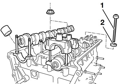
- Oil bolts (1) and washers (2) and screw them in as far as possible.
- Check that the engine block and cylinder head gasket are correctly aligned; if necessary use a whetstone to remove protruding edges of the gasket.
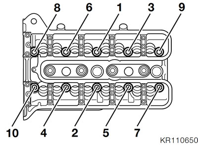
- Tighten the cylinder head bolts in the correct sequence as shown to 20 Nm.
- Install angle-of-rotation gauge, BMW No. 11 2 500, with two Torx inserts T 50, BMW No. 00 2 630.
- Tighten the cylinder head bolts in the correct sequence as shown through a further 90°.
- Install the bucket tappets.
- Install the camshafts.
See below.
- Install the temperature sensor.
See Group 61.
Tightening torque:
- Cylinder head bolts
- Initial tightening — 20 Nm
- Wrench angle — 90°
- Bearing caps, camshaft — 10 Nm
- Temperature sensor — 30 Nm
- Identification marks, camshafts
- Inlet — 2 grooves behind the thrust bearing
- Exhaust — 1 groove behind the thrust bearing
- Identification marks, camshaft bearing caps
- Inlet side — odd numbers
- Exhaust side — even numbers
Consecutive numerical order from front (timing end) to rear.
Caution: Centre the pistons in the cylinders (cylinder 1 approx. 90° before top dead centre) to avoid damaging the valves and pistons.
- Oil the camshaft bearing journals.
- Insert the camshafts so that the tips of the cams are clear.
- Install the inner bearing caps first.
- Install the thrust bearing (timing end) with slide rail last and do not tighten it until the chain sprok-kets have been installed.
- Tighten the bearing caps uniformly, working from the inside outwards.
Tightening torque:
- Bearing cap — 10 Nm
Installing timing chain
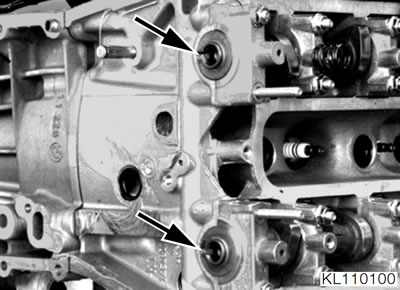
- Turn the camshafts until the grooves at the timing end (arrows) point toward the crankshaft.
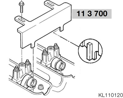
- Place aligning device, BMW No. 11 3 700, in position and secure it to the camshaft bearing caps.
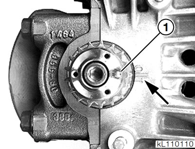
- Turn the crankshaft another 90° in the normal direction of rotation. The piston of cylinder 1 must now be at top dead centre. The pin (1) on the crankshaft is aligned with the mark (arrow) on the crankcase.
- Place the timing chain in guide rail (2).
- Insert bushing (arrow) between slots of guide rail.
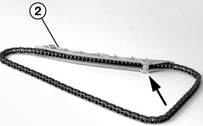
- Press the guide rail (3) with timing chain and bushing onto the locating pin.
- Install the snap rings (1) and washers (2) for the guide rail on the two locating pins.
- Slip the chain onto the crankshaft gear.
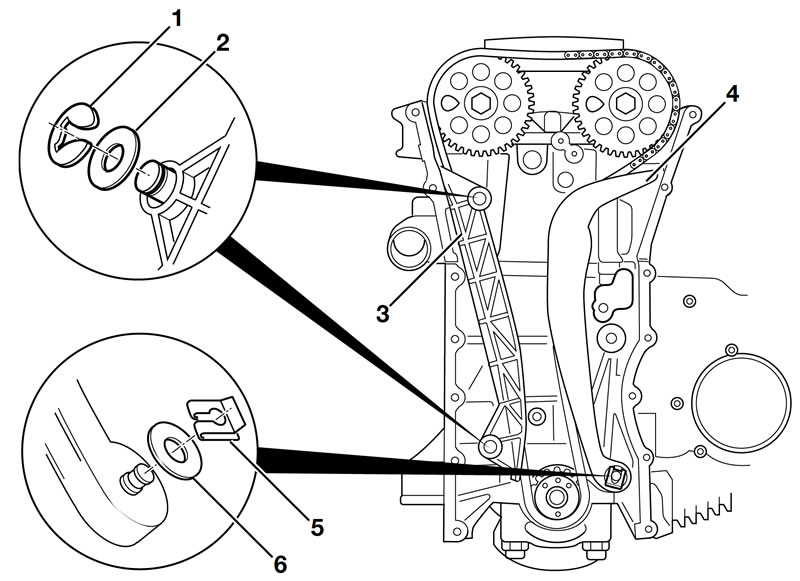
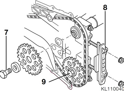
- Install the sprocket of the inlet camshaft such that the timing chain is tensioned between the sprocket and the crankshaft gear.
- Install screw (7) until seated.
- Install guide rail (8).
- Press the tensioning rail (4) onto the locating pin and install washer (6) and keeper (5).
- Install the sprocket of the exhaust camshaft such that the timing chain is correctly tensioned between the two sprockets.
- Install screw (9) until seated.
- Tighten the bearing caps with guide rail (8).
- Remove the aligning device, BMW No. 113700.
- Tighten the chain sprockets, holding the hexagon on the camshaft to prevent it from turning.
Tightening torque:
- Bearing cap — 10 Nm
- Chain sprockets — 56 Nm
Installing timing case cover
- Insert O-ring (1) for chain tensioner into timing case cover.
- Install chain tensioner in timing case cover.
- Prevent chain tensioner from moving with pin, BMW No. 11 6 740.
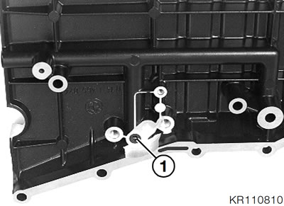
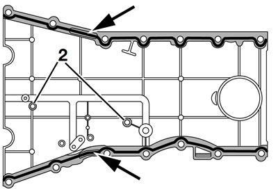
- Clean and degrease the sealing face, apply a thin coat of Omni VISC 1002, taking care not to omit the area around the bores marked above (2), see black line on sealing face shaded grey.
- Fill the expansion grooves (arrows) with sealing compound.
Note: Remove excess sealing compound with a spatula.
- Introduce the cables for the oil-pressure switch and water temperature switch through the cable duct.
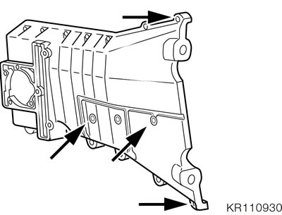
- Install the timing case cover and tighten the securing screws. Make sure that the long screws are installed in the correct positions (arrows).
- Remove the chain tensioner pin and tighten the screw plug.
- Turn the engine over and check the relative positions of the camshaft sprockets and the crankshaft gear.
Tightening torque:
- Chain tensioner to timing case cover — 9 Nm
- Timing case cover — 9 Nm
- Screw plug for pin — 9 Nm
Checking valve clearances
- Turn the engine over by turning the crankshaft (counter-clockwise).
- Measure valve clearance with feeler gauge.
Valve clearances:
- Inlet — 0.15.0.20 mm (0.005...0.007 in)
- Exhaust — 0.25.0.30 mm (0.009...0.011 in)
- Remove the camshaft if valve clearance has to be adjusted.
- Replace the corresponding bucket tappets.
Adjusting valve clearances
See Group 00.
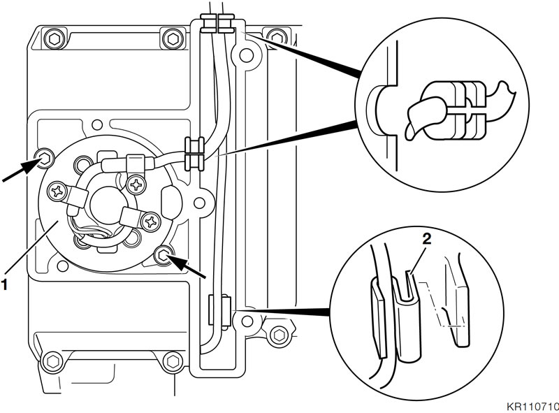
Installing ignition pulse generator
- Mount adjusting disc and rotor on crankshaft and tighten.
- Reinstall magnetic gate (1) in its original position, as marked.
- Tighten screws (arrows) with washers and semicircular washers.
Tightening torque:
- Rotor — 4 Nm
- Magnetic gate — 6 Nm
Caution: Set the ignition timing.
- Run the wire to the ignition pulse generator through a rubber grommet in the timing case cover.
- Secure the wires for the oil pressure telltale and water pump temperature sensor with clip (2).
- Install the cover with gasket.
Tightening torque:
- Ignition pulse generator cover — 9 Nm
Installing combined oil/water pump
Caution: Tighten the clutch housing before installing the oil/ water pump, so that the output shaft cannot damage the pump housing.
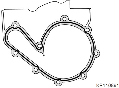
- Check that sealing face of the pump housing is clean and degreased and apply a thin coat of Omni VISC 1002, see black line on sealing face with grey shading.
- Place O-ring on water passage.
- Position the drive pinion on the output shaft.
- Place pump housing in position and install screws, but do not tighten.
Note: Turn the crankshaft to centre the gearwheels, tightening the screws further at the same time.
- Fully tighten the screws.
- Check for any noticeable play at any position of the water pump gearwheel.
Tightening torque:
- Pump housing to crankcase — 10 Nm
- Run the wires for the oil pressure telltale and water pump temperature sensor through the hole in the pump housing and connect them.
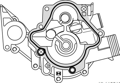
- Check that sealing face of the pump housing cover is clean and degreased and apply a thin coat of Omni VISC 1002, see line on sealing face with grey shading.
- Install the pump housing cover and tighten the securing screws.
Tightening torque:
- Pump housing cover — 10 Nm
Installing crankcase cover
- Apply a thin coat of Three Bond 1209 to the areas where the crankcase, intermediate flange and crankcase cover meet, and to the sealing faces on the crankcase, timing case cover and crankcase cover.
- Install the crankcase cover with gasket.
- Install all bolts until seated.
- Tighten the bolts in diagonally opposite sequence, working from the inside outwards.
Tightening torque:
- Crankcase cover — 9 Nm
Installing cylinder head cover
- Install the spark plugs and ignition leads.
See Group 12.
Tightening torque:
- Spark plug — 20 Nm
- Install the cylinder head cover gasket with the half moons first. The marks at the front and rear of the gasket and the cylinder head cover must coincide.
- Apply a thin coat of Three Bond 1209 at the areas where the cylinder head, timing case cover and cylinder head cover meet and at the half moons (arrows).
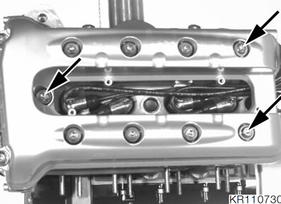
Note: Do not forget the contact springs.
- Install the cylinder head cover. Insert the front centre screw (timing end, arrow) and both rear screws (arrows) in order to locate the gasket.
- Install all screws until seated.
- Tighten the screws in diagonally opposite sequence, working from the inside outwards.
- Mount the heat shield on the cylinder head cover.
Tightening torque:
- Cylinder head cover — 9 Nm
- Securing screws for heat shield — 5 Nm
