Checking the key switch
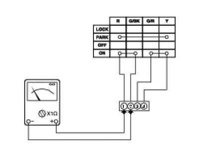
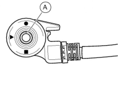
Disconnect the key switch (A) from the electrical system by opening its connection (see Routing of wiring on frame) and use a multimeter to check its internal connections as follows:
turn the key to OFF and connect a multimeter to contacts (1) and (4) to check electrical continuity (Using a multimeter to check the electrical systems concerning operation of the multimeter). The resistance reading should be near zero and, if present, the audible continuity signal should be emitted;
turn the key to ON and connect the multimeter to contacts (1) and (2) and then to (3) and (4) to check for electrical continuity. The resistance reading should be near zero and, if present, the audible continuity signal should be emitted;
turn the key to PARK and connect the multimeter to contacts (1) and (4) to check electrical continuity. The resistance reading should be near zero and, if present, the audible continuity signal should be emitted;
turn the key to LOCK and connect the multimeter to contacts (1) and (4) to check for electrical continuity. The resistance reading should be near zero and, if present, the continuity sound signal should be emitted.


Note: The same checks can also be performed using the "DDS" tester (DDS tester).
Checking the sidestand switch
Remove the switch from the sidestand (Removal of the sidestand) and disconnect the main wiring harness connector from the switch (see Routing of wiring on frame).
Use an analogue or digital multimeter (Using a multimeter to check the electrical systems) to check operation of the switch (see table).


Note: The same checks can also be performed using the "DDS" tester (DDS tester).
| Pos. pin (A) | Consumers | Rating. |
| l - s | 0 | X |
| s - n | X | 0 |
| Multimeter pos. | Green/Green White | Green/Yellow Black |
0 = Open contact
X = Closed contact
