Warning! Some gasoline will drain from the individual components when disconnected from the fuel pump/filters/fuel level sender assembly. Thoroughly wipe up any spilled fuel immediately. Dispose of rags in a suitable manner. Gasoline is extremely flammable and highly explosive. Inadequate safety precautions could result in death or serious injury.
Removal
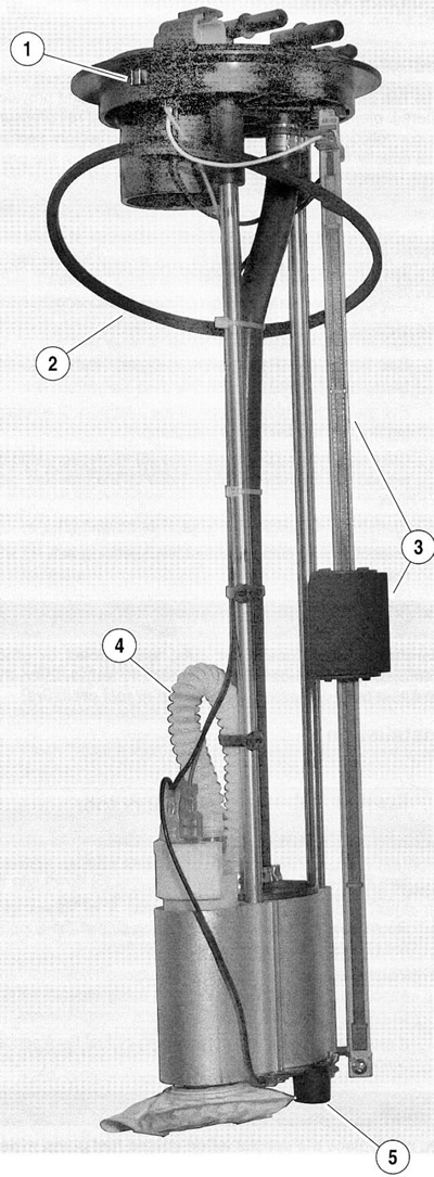
1. See Figure 4-6. Remove yellow wire lead and the double black wire leads from the rheostatic slide (3).

Figure 4-6. Fuel pump/filters/fuel level sender assembly: 1. Mating tabs to fuel tank notch; 2. Quad-seal; 3. Rheostatic slide and fuel level sender float; 4. Crossover tube; 5. Rubber spacer/bumper
2. Inspect and replace as required all fuel level sender wiring.
3. Remove the retaining screw at the bottom of the rheostatic slide (3).
4. Pull the rheostatic slide (3) from its slot in the top plate and remove the fuel level sender float (3).
Installation
1. See Figure 4-6. Slide rheostatic slide with fuel level sender float (3) into notch in top plate. Orient the scale so that the graduated side of the slide faces the fuel level wire connector on the top plate.
2. With the fuel level sender float on the slide (3) so that the half-round side faces out, thread in and tighten the retaining screw into the stop bracket at the bottom of the rheostatic slide (3).
3. Attach the yellow wire lead to the graduated side of the rheostatic slide (3) and the double black lead to the opposite side.
4. Install fuel pump/filters/fuel level sender assembly into gas tank. See 4.2 Fuel pump/filters/fuel level sender assembly.
5. Verify that the fuel gauge indicates the corresponding fuel level after installing the fuel pump/filters/fuel level sender assembly.
