| PART NO. | SPECIALTY TOOL |
| HD-45324 | Fuel cap remover/installer |
1. Unlatch and open seat. Remove fuel cap, remove fuel filler boot, and replace fuel cap.
Warning! Gasoline is extremely flammable and highly explosive. Always stop the engine when refueling or servicing the fuel system. Do not smoke or allow open flame or sparks near the work site. Inadequate safety precautions could result in death or serious injury.

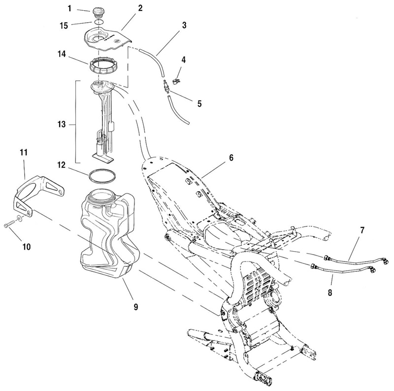
Figure 4-1. Fuel system: 1. Fuel cap; 2. Fuel filler boot; 3. Vapor vent hose; 4. Vapor valve frame clip; 5. Vapor valve; 6. Fender skin weldment; 7. Pressure fuel line; 8. Return fuel line; 9. Fuel tank; 10. Bracket bolts; 11. Fuel tank bracket; 12. Quad seal; 13. Fuel pump/filters/fuel level sender assembly; 14. Lock ring; 15. Fuel cap o-ring
Warning! The gasoline in the fuel supply line downstream of the fuel pump is under high pressure (400 kPa, 58 psi). To avoid an uncontrolled discharge or spray of gasoline, always purge the system of high pressure gas before removing the fuel supply line from the fuel tank. Gasoline is extremely flammable and highly explosive. Inadequate safety precautions could result in death or serious injury.
2. Purge the fuel supply line of high pressure gasoline.
- a. See Figure 4-3. Disconnect the fuel module connector (5) from the top plate (1).
- b. Start the engine and allow the vehicle to run.
- c. When the engine stalls, operate the starter for 3 seconds to remove any remaining fuel from the fuel lines.

Figure 4-3. Fuel tank top plate: 1. Top plate; 2. Vapor vent hose; 3. Pressure fuel line; 4. Return fuel line; 5. Fuel module connector; 6. Thread start pointer; 7. Wiring harness (resistive plug/purge solenoid); 8. Lock ring
3. Remove right side cover.
4. See Figure 4-2. Remove maxi-fuse.

Figure 4-2. Maxi-fuse
5. Remove airbox. See 1.4 Airbox and air filter.
Warning! To protect against shock and accidental start-up of vehicle, disconnect the negative battery cable before proceeding. Inadequate safety precautions could result in death or serious injury.
6. Disconnect the negative battery cable.
7. Determine how long before the assembly can be reinstalled.
- a. If the fuel tank is to be left unattended for any length of time, remove the fuel cap and drain the fuel tank. Use a pump or siphon and an approved gasoline storage container of sufficient capacity.
- b. If the fuel pump/filters/fuel level sender assembly is to be repaired and reinstalled immediately, the open fuel tank can be covered temporarily until the fuel pump/filters/fuel level sender assembly is reinstalled.
Warning! Some gasoline will drain from the fuel lines when disconnected from the fuel tank top plate. Thoroughly wipe up any spilled fuel immediately. Dispose of rags in a suitable manner. Gasoline is extremely flammable and highly explosive. Inadequate safety precautions could result in death or serious injury.
8. See Figure 4-3. At the fuel rail, disconnect the larger pressure fuel line (3) and the smaller return fuel line (4) by pressing blue buttons with thumb and first finger. Then disconnect both fuel lines from the fuel tank top plate. Pull the lines out of the rotational path of the lock ring.
9. Use opposite thumbs to push the vapor vent hose (2) off of the outlet tube.
10. Assure that all components are out of the rotational path of the lock ring.
Note. Motorcycles not equipped with the H-D Security System will have the siren connector terminated to a cap attached to the wiring harness of the fuel module connector. Pull the siren connector and press the wiring harness out of the way before turning lock ring.
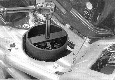
11. See Figure 4-4. Use FUEL CAP REMOVER/INSTALLER (HD-45324) to unthread and lift off the lock ring.

Figure 4-4. Fuel cap remover/installer (HD-45324)
Warning! Gasoline is extremely flammable and highly explosive. When servicing the fuel system, do not smoke or allow open flame or sparks in the vicinity. Inadequate safety precautions could result in death or serious injury.
12. Lift the fuel pump/filters/fuel level sender assembly out of the fuel tank.

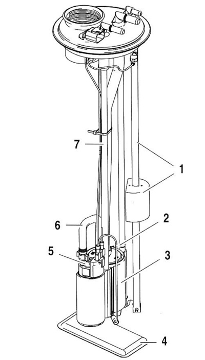
Figure 4-5. Fuel pump/filters/fuel level sender assembly: 1. Sending unit; 2. Pressure side filter; 3. Bracket; 4. Suction side filter; 5. Fuel pump; 6. Crossover hose; 7. Support rod
13. Cover the fuel tank opening or drain the fuel tank as required.
