
XRV750-L to N (1990 to 1992) models
Check - warning light circuit
1. XRV750-L to N (1990 to 1992) models are fitted with a fuel warning light circuit checker (see illustration 15.2b). When the ignition is switched ON, both low fuel warning lights (one red. one orange) should come on for a few seconds, then extinguish. If they do not, first check the fuses, then check the bulbs (see Chapter 9). If they are good, check the fuel sensor and its circuit (see below).
2. If all is good so far, disconnect the wiring connector from the circuit checker, located below the instrument cluster on the right-hand side. With the ignition switch ON. check for battery voltage between the black (+) and green/white (-) wire terminals on the connector. There should be battery voltage. If not, check the wiring and connectors for faults, referring to the Wiring Diagrams at the beginning of the Chapter. If there is voltage, the checker is faulty and must be replaced with a new one.
Check - fuel sensor circuit
3. The circuit consists of the fuel level sensor mounted in the fuel tank and the low fuel warning light mounted in the instrument panel. If the system malfunctions first check that the bulb and fuses are good (see Chapter 9).
4. Remove the left-hand fairing side panel (see Chapter 8). Disconnect the fuel level sensor wiring connector, located below the tank on the left-hand side. Also disconnect the wiring connector from the circuit checker, located below the instrument cluster. Using an insulated jumper wire, short between the orange/white and green wire terminals on the loom side of the sensor wiring connector. Turn the ignition switch ON. If the orange warning light comes on. check the orange/white and green wires between the connector and the sensor itself in the tank for loose or broken connections. If the wiring is good, replace the sensor with a new one. If the orange warning light does not come on, check wiring between the connector and the instrument cluster for loose or broken connections.
5. Now short between the grey/black and green wire terminals on the loom side of the sensor wiring connector. Turn the ignition switch ON. If the red warning light comes on, check the grey/black and green wires between the connector and the sensor itself in the tank for loose or broken connections. If the wiring is good, replace the sensor with a new one. If the orange warning light does not come on, check wiring between the connector and the instrument cluster for loose or broken connections.
Replacement
6. See Chapter 9 for replacement of the warning light bulb.
7. To replace either sensor, remove the fuel tank and drain it (see Section 2). Disconnect the wiring connectors from the sensor.
8. Unscrew the sensor and draw it out of the tank. Discard the О-ring. Fit a new О-ring onto the sensor. Apply a smear of suitable sealant to the upper portion of the sensor threads, then screw it into the tank and tighten it to the torque setting specified at the beginning of the Chapter.
9. Install the tank (see Section 2). and check carefully for leaks before using the bike.
XL650V models
Check
10. The circuit consists of the fuel level sender unit mounted in the fuel tank and the gauge mounted in the instrument panel. If the system malfunctions first check that the fuses are good, then check the power input to the instrument cluster (see Chapter 9, Sections 5 and 16).
11. Remove the fuel gauge sender unit (see below). Connect an ohmmeter across the sender unit wire terminals then check the resistance reading whilst moving the float arm slowly from the full to empty position and back again. Compare the readings obtained to those given in the Specifications. Not only should the full and empty readings be as specified but the value should change evenly and progressively as the float arm is moved. If not the sender unit is faulty and should be renewed.
12. If the sender unit functions correctly, connect it to the wiring connector then switch the ignition ON. Move the float arm up and down again and check that the operation of the gauge corresponds to the movement of the arm. If the gauge does not function correctly, switch off the ignition and remove the fairing (see Chapter 8).
13. Disconnect the wiring connectors from the instrument cluster and fuel gauge sender unit. Use an ohmmeter to check for continuity in the grey/black and green/black wires between the cluster and sender unit, using the relevant Wiring Diagram at the end of Chapter 9 to make sure you have the correct instrument cluster connector. Also check for continuity to earth (ground) in the green/black wire. If continuity (zero resistance) is not present, repair/replace the wiring harness. If continuity exists, then the gauge is probably faulty.
Replacement
14. See Chapter 9 for replacement of the fuel gauge.
15. To replace the sender unit, remove the fuel tank and drain it (see Section 2).
16. Unscrew the nuts securing the sender and carefully manoeuvre it out of the tank, taking care not to bend the float arm (see illustration). Discard the O-ring.
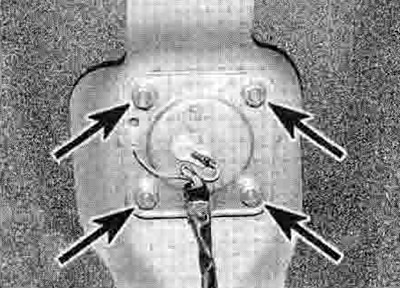
16.16. Fuel level sender mounting nuts (arrowed)
17. Fit a new О-ring onto the sensor and install it in the tank. Tighten the nuts evenly and a little at a time to the torque setting specified at the beginning of the Chapter.
18. Install the tank (see Section 2), and check carefully for leaks before using the bike.