
Check
1. On XL600V models and XRV750-L to N (1990 to 1992) models remove the right-hand side panel (see illustration). On XL650V and XRV750-P models onwards (1993-on) remove the left-hand side panel (see illustrations). Either trace the wiring from the regulator/rectifier and disconnect it at the connectors, or disconnect the connector from the regulator/rectifier, according to model. Check the connectors for loose, damaged or corroded terminals.

33.1a. Regulator/rectifier (arrowed) - XL600V

33.1b. Regulator/rectifier (arrowed) - XL650V

33.1c. Regulator/rectifier (arrowed) - XRV750-P models onward (1993-on)
2. Set the multimeter to the 0-20 de volts setting. Connect the meter positive (+) probe to the red/white wire terminal (use either terminal where there are two, and check both) on the loom side of the connector and the negative (-) probe to a suitable ground (earth) and check for voltage. Full battery voltage should be present at all times (i.e. with the ignition OFF). On XL600V-H to К (1987 to1989) models and XRV750-L and M (1990 and 1991) models, perform a similar check for Cattery voltage at the black wire terminal, this time with the ignition ON.
3. Switch the multimeter to the resistance (ohms) scale. Check for continuity between the green wire terminal on the loom side of the connector and ground (earth). There should be continuity.
4. On XRV750 models, set the multimeter to the K-ohms (ohmmeter) scale and measure the resistance between each of the terminals as indicated by the table for your model (see illustrations). The readings should be within the range shown. Honda provide no such figures for XL models, but you could use the XRV figures as a guide for checking the internal circuitry. Usually a fault is identifiable by the absence or presence of infinite or zero resistance when there should in fact be a measurable amount.
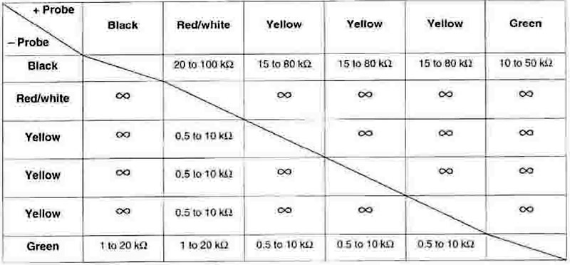
33.4a. Regulator/rectifier test details - XRV750-L to N (1990 to 1992) models

33.4a. Regulator/rectifier test details - XRV750-P models onward (1993-on)
5. If the above checks do not provide the expected results check the wiring and connectors between the battery, regulator/rectifier and alternator for shorts, breaks, and loose or corroded terminals (see the wiring diagrams at the end of this book).
6. If the wiring checks out. the regulator/rectifier unit is probably faulty. Take it to a Honda dealer for confirmation of its condition before replacing it with a new one. Alternatively obtain a known good one to use as a substitute, then check whether the fault has been corrected.
Replacement
7. On XL600V models and XRV750-L to N (1990 to 1992) models remove the right-hand side panel (see illustration 33.1a). On XL650V and XRV750-P models onwards (1993-on) remove the left-hand side panel (see illustrations 33.1b or c). Either trace the wiring from the regulator/rectifier and disconnect it at the connectors, or disconnect the connector from the regulator/rectifier. according to model. Free the wiring from any clips or ties and feed it back to the regulator/rectifier.
8. Unscrew the two nuts or bolts securing the regulator/rectifier, noting any earth wires, and on XL600 models the rear brake master cylinder reservoir, secured by them, and remove the regulator/rectifier.
9. Installation is the reverse of removal.