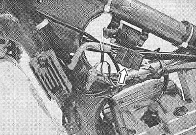
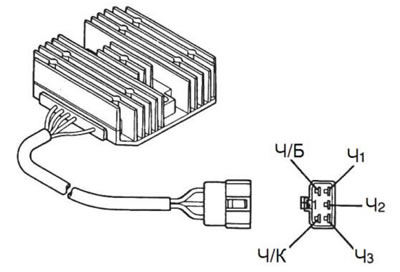
Disconnect the regulator/rectifier connector.

Measure the voltage between the lead terminal wires using a multi-tester as shown in the figure. If the voltage is not within the specified value, replace the regulator/rectifier with a new one.
09900-25008: multitester
Tester Pen Installation: Diode Test

Wire color: H: Black; B/C: Black with Red stripe; B/W: Black with White stripe
Magnitude: Volts
| Tester positive probe | ||||||
| Negative tester probe | B/C | Ch1 | Ch2 | Ch3 | B/W | |
| B/C | 0,4-0,7 | 0,4-0,7 | 0,4-0,7 | 0,5-1,2 | ||
| Ch1 | * | * | * | 0,4-0,7 | ||
| Ch2 | * | * | * | 0,4-0,7 | ||
| Ch3 | * | * | * | 0,4-0,7 | ||
| B/W | * | * | * | * | ||
* Readings: no less than 1.4 V (multitester battery voltage).
Note. If the tester shows below 1.4V when the tester probes are not connected, replace the multitester battery.
