Removing the cylinder head cover
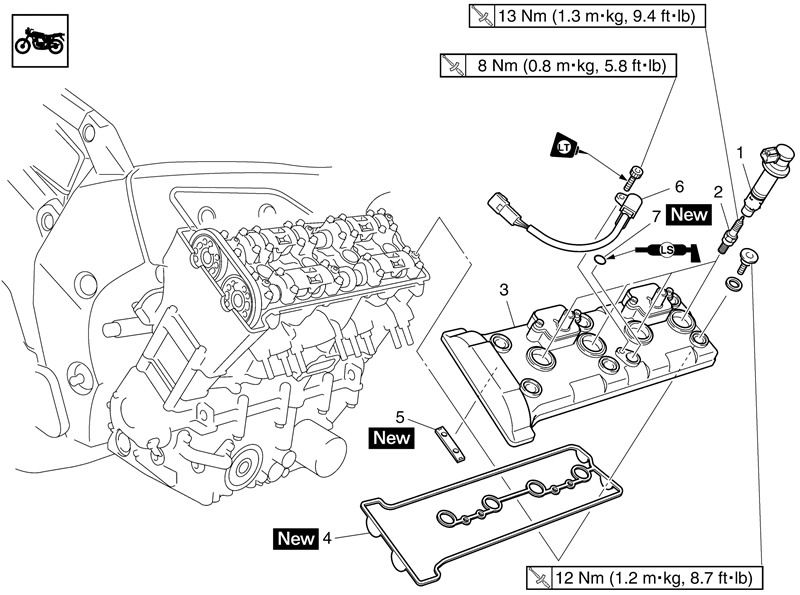
| Order | Job/Parts to remove | Quantity | Remarks |
| Fuel tank | Refer to «Fuel tank». | ||
| Throttle body assembly | Refer to «Throttle bodies». | ||
| Radiator assembly | Refer to «Radiator». | ||
| Air cut-off valve | Refer to «Air induction system». | ||
| 1 | Ignition coil | 4 | |
| 2 | Spark plug | 4 | |
| 3 | Cylinder head cover | 1 | |
| 4 | Cylinder head cover gasket | 1 | |
| 5 | Timing chain guide (top side) | 1 | |
| 6 | Cylinder identification sensor | 1 | |
| 7 | O-ring | 1 |
Removing the camshafts
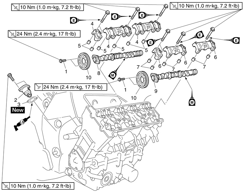
| Order | Job/Parts to remove | Quantity | Remarks | ||
| Pickup rotor cover | Refer to «Crankshaft position sensor». | ||||
| 1 | Camshaft sprocket bolt | 4 | Loosen. | ||
| 2 | Timing chain tensioner | 1 | |||
| 3 | Timing chain tensioner gasket | 1 | |||
| 4 | Intake camshaft cap | 3 | |||
| 5 | Dowel pin | 6 | Refer to «Removing the camshafts». | ||
| 6 | Exhaust camshaft cap | 3 | |||
| 7 | Dowel pin | 6 | Refer to «Removing the camshafts». | ||
| 8 | Intake camshaft | 1 | |||
| 9 | Exhaust camshaft | 1 | |||
| 10 | Camshaft sprocket | 2 |
1. Remove:
- Pickup rotor cover
Refer to «Crankshaft position sensor».
2. Align:
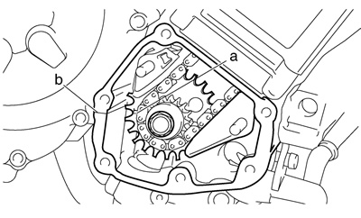
- «T» mark «a» on the pickup rotor (with the crankcase mating surface «b»)
a. Turn the crankshaft clockwise.
b. When piston #1 is at TDC on the compression stroke, align the «T» mark «a» on the pickup rotor with the crankcase mating surface «b».
Note: TDC on the compression stroke can be found when the camshaft lobes are turned away from each other.
3. Loosen:
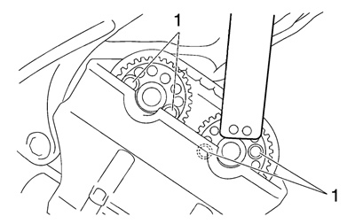
- Camshaft sprocket bolts «1»
Camshaft wrench: 90890-04143 YM-04143
4. Remove:
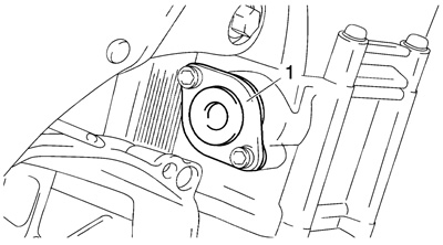
- Timing chain tensioner «1»
- Gasket
5. Remove:
- Camshaft caps «1»
- Dowel pins
Caution! To prevent damage to the cylinder head, camshafts or camshaft caps, loosen the camshaft cap bolts in stages and in a crisscross pattern, working from the outside in.

6. Remove:
- Intake camshaft «1»
- Exhaust camshaft «2»
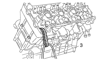
Note: To prevent the timing chain from falling into the crankcase, fasten it with a wire «3».

