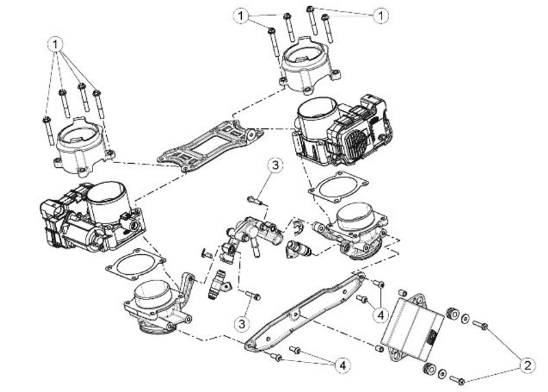
| pos. | Description | Type | Quantity | Torque | Notes |
| 1 | Intake union fastener screw | M6 | 8 | 12 Nm (8.85 lbf ft) | Loctite 242 |
| 2 | RBW control unit fastener screw | M5 | 2 | 3.50 Nm (2.58 lbf ft) | Loctite 242 |
| 3 | Injector fastener screw | M6 | 2 | 12 Nm (8.85 lbf ft) | Loctite 242 |
| 4 | Injection Throttle Body fastener screw | M6 | 8 | 12 Nm (8.85 lbf ft) | Loctite 242 |
Ride by wire
Operating logic
Those riding motorbikes do not require a specific throttle valve opening from their engines but actually a specific torque. The Ride by Wire system has been so designed that the throttles of the throttle bodies are mechanically isolated from the throttle control; their actuation depends exclusively on 2 electrical motors controlled by the control unit. Therefore, there is a "Throttle map" to which the control unit refers in order to decide the position at which the throttle valves should be and at what speed they should reach the pre-set position. The main parameters which influence the throttle map are:
- Throttle position and opening/closing speed
- Engine rpm
- Inlet pressure read at each inlet manifold
- Rear and front throttle valve position
- Air temperature
The functions required from the Marelli control unit therefore are:
- 1. Ride by Wire system control (throttle map)
- 2. Injection/ignition control
- 3. System safety checks
1 - Ride by Wire system control
Throttle grip position sensor
The throttle grip is the part to which the throttle control cables arrive; its task is to translate the rider's power request into an electrical signal to be sent to the electronic control unit. The two throttle cables (opening and closing) actuate on a scroll mounted on a shaft and which is sent back to its home position by a return spring.
On the shaft covers there are 2 double track potentiometers (4 control tracks) by means of which the torque demand is read (and checked).
Marelli 5DM electronic control unit
Besides the regular control functions of the injection system, it supervises the throttle bodies: Through the throttle grip position sensor, it reads the torque demand and, through the THROTTLE MAP, it decides the throttle opening and sends the command to the throttle valve control unit. It checks the correct operation of each component (Self-diagnosis), of the system (Safety), and carries out the emergency procedure (Recovery).
EFI throttle control unit
The control unit receives the target throttle opening to be carried out and it actuates on the control acting on the throttle body motors.
It checks (through the throttle position sensor signal) that the throttle bodies have reached the target position.
It communicates the position reached to the Marelli control unit. It does not actuate on Safety strategies.
Throttle Body
The two throttle bodies are made up of:
- Throttle valve with 2 return springs for the controlled minimum opening position.
- DC electrical motor
- Tinned double throttle position sensors with magnetic control (contactless)
The throttle bodies do not require any maintenance and cannot be overhauled. In case of electric or mechanic malfunction, replace the whole unit.
Pressure sensors
The pressure sensors (one per cylinder) are fundamental not only for the injection map at low and stabilised speeds but also for checking the Ride by Wire system: their signal is connected to a TORQUE CHAIN for checking the correct opening of the throttle valves.
Intake air temperature sensor
The signal coming from the sensor is used to calculate the estimated torque since the oxygen in the air also depends on its density which varies according to temperature.
2 - Injection/ignition control
Map for injection type (alpha-D)/rpm where:
- Alpha is the throttle position
- D is the pressure measured at inlet ducts
- Rpm are the engine revolutions
- At idle and for slow and stabilised speeds D/n
- For medium-high throttle openings alpha/n
- For temporary speed (speed change) alpha/n
- The main parameters that correct the injection map are:
- Engine temperature
- Atmospheric pressure (calculated)
- Lambda probe signal
- Air temperature
3 - System safety checks
The checks are structured in several levels:
- Level 1 - sensor correct operation
- Level 2 - comparison between requested torque and estimated torque generated by the engine
- Level 3 - a microprocessor controls the correct operation of the regular microprocessor
The consequent maintenance operations may be of different gravity according to the level and the defective component:
A. the malfunction does not affect riding in safety, the warning light turns on, the word Service is displayed, the signal recovery value considered not reliable is used and the engine works regularly.
B. the malfunction may affect riding in safety, the warning light turns on, the message Urgent Service is displayed, the torque demands are not fully activated (reduced torque).
C the malfunction may affect riding in safety, the warning light turns on, the message Urgent Service is displayed, the engine operates in Limp Home function (accelerated idle), the throttles which are at the position exclusively depending on the springs are not moved. The engine may shut off during the operation if it is running at idle speed and the gear is in neutral.
D. the malfunction may affect riding in safety, the warning light turns on, the message Urgent Service is displayed, the engine stops running.
