Removing rear swinging arm
- Remove the right and left front and rear footrest plates.
See Group 46.
- Remove left trim panel and battery cover.
See Group 46.
- Remove exhaust system.
See Group 18.
- Remove rear wheel.
See Group 36.
- Remove the inductive signal transmitter.
See Group 61.
- Remove brake caliper.
See Group 34.
- Secure brake caliper with inductive sensor to rear frame, using a cable tie.
- Remove rear wheel drive unit.
See above.
Caution: Note high release torques for lock ring and left and right threaded rings and bearing studs.
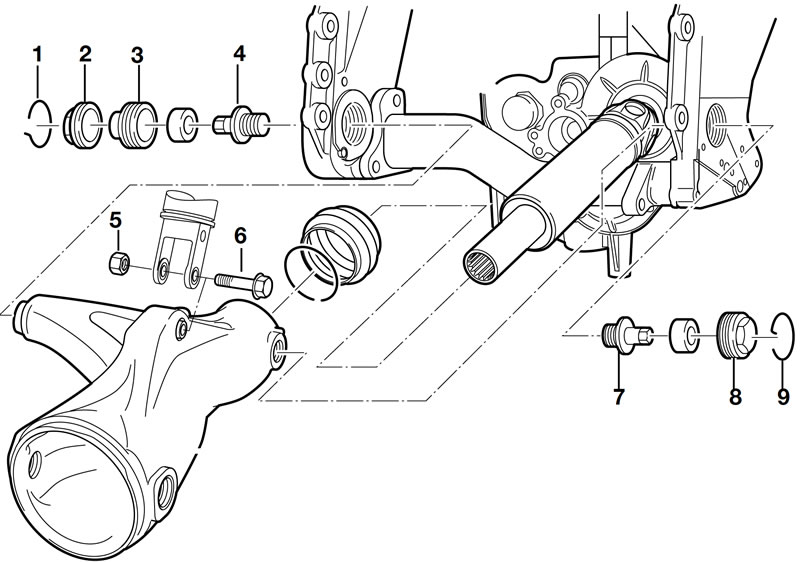
- Remove retaining rings (1, 9).
- Remove right threaded ring (8).
- Remove lock ring (2).
- Remove left threaded ring (3).
- Using socket wrench insert, BMW No. 33 6 643, slacken bearing studs (4, 7) on left and right.
- Remove screws (5, 6) for shock absorber.
- Push shock absorber up and secure to frame with cable ties.
- Remove bearing studs (4, 7) on left and right.
- Pull swinging arm off drive shaft.
Removing and installing flexible gaiter
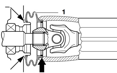
- Take out the inner circlip (arrow) and pull the flexible gaiter (1) out of the swinging arm.
- When installing, coat inner and outer sealing lips (arrows) with Staburags NBU 30 PTM.
Removing and installing threaded ring bearings
Removing bearing from left/right threaded ring
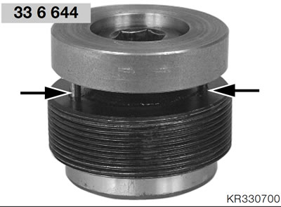
- Engage pins (arrows) of press-out tool, BMW No. 33 664 4, in bores of threaded ring.
- Press the left/right bearing out of the threaded ring.
Installing bearing in left/right threaded ring
Caution: Install with the open side of the bearing facing the threaded ring.
- Grease the bearing.
- Press the bearing into the left/right threaded ring.
Removing drive shaft
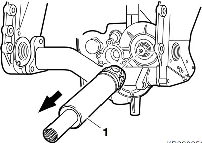
- Use a tyre lever or similar tool to press off the front drive shaft (1).
Caution: Do not scratch painted components: if necessary, use a rubber mat.
Note: If necessary, remove/install the circlip in the joint element.
Checking universal joint for wear
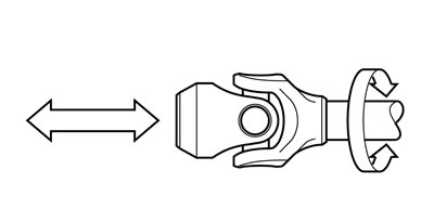
- Determine endplay and radial play (arrows).
- Make sure that no play is perceptible at universal joint.
Installing drive shaft
- Coat the output shaft splines with Optimoly MP 3.
- Slide the front drive shaft on to the output shaft.
- Snap the circlip into position by striking the drive shaft lightly with a plastic-faced hammer.
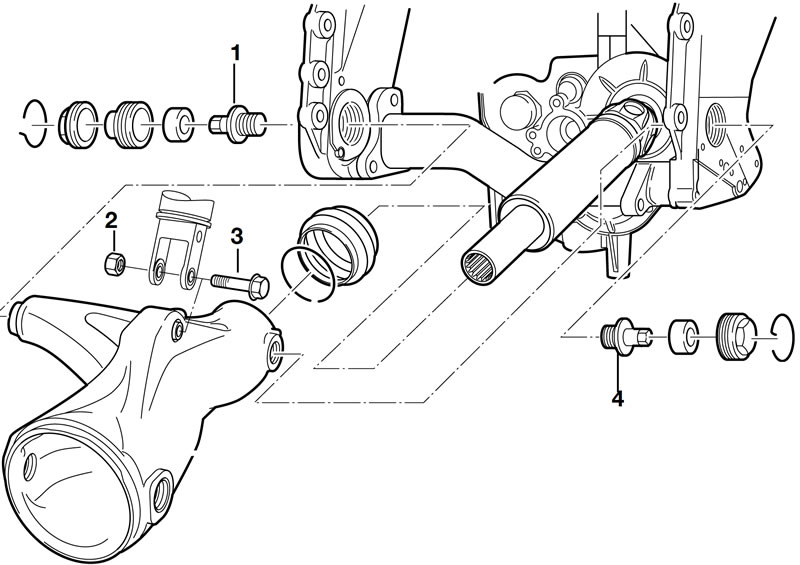
Installing rear swinging arm
- Slide swinging arm over drive shaft and push forward as far as possible until rubber gaiter clicks into place on housing neck.
- Screw in left/right bearing studs (1,4).
- Tighten screws (2, 3) securing suspension strut to swinging arm.
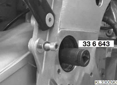
- Using socket wrench insert, BMW No. 33 6 643, tighten bearing studs (1, 4) on left and right.
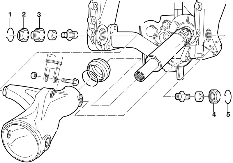
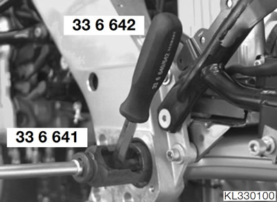
- Tighten the right threaded ring (4).
- Tighten the left threaded ring (3).
- Hold left threaded ring (3) with socket wrench, BMW No. 335642, to prevent it turning and tighten locking ring (2) with socket, BMW No. 336641.
- Insert circlips (1, 5) on left and right with the hook toward the outside.
Tightening torques:
- Swinging arm to frame
- Release the left/right bearing stud — 160 Nm
- Threaded ring, right — 200 Nm
- Threaded ring, left — 10 Nm
- Lock ring — 160 Nm
- Suspension strut to swinging arm — 50 Nm
- Install the rear wheel drive.
See above.
- Install brake caliper.
See Group 34.
- Install the inductive signal transmitter.
See Group 61.
- Install the rear wheel.
See Group 36.
- Install exhaust system.
See Group 18.
- Install left trim panel and battery cover.
See Group 46.
- Install the right and left front and rear footrest plates.
See Group 46.
Removing and installing suspension strut
- Remove left and right fairing side sections.
See Group 46.
- Remove left and right rear footrest plates.
See Group 46.
- Remove the right-hand battery cover.
See Group 46.
- Remove fuel tank.
See Group 16.
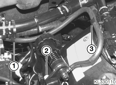
- Remove screw (2) securing handwheel for spring-strut adjustment.
- Disengage line for spring-strut adjustment from holders (1, 3) and pull handwheel down and away.
- Remove protective cap from top spring-strut screw.
- Slightly raise rear wheel to ease load.
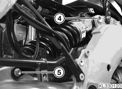
- Remove screw (5) securing spring strut at bottom.
- Remove screw (4) securing spring strut at top and remove spring strut.
- Installation is the reverse of the removal procedure: pay particular attention to the following.
- Clip line for spring-strut securely into holders (1, 3).
Tightening torques:
- Suspension strut to swinging arm — 50 Nm
- Suspension strut to frame — 43 Nm
- Handwheel to rear frame — 21 Nm
