
Inspection III
Checking valve clearances
Caution: Never unscrew the spark plugs before measuring valve clearances. Oil-carbon particles could become lodged behind the exhaust valve head and falsify the measurement.
The engine temperature must not exceed 35°C (95°F) when valve clearance is measured.
- Remove fairing side section, engine spoiler and left skirt bracket.
See Group 46.
- Remove cylinder head cover.
- Turn the engine by the rear wheel.
- Measure valve clearance using a feeler gauge and make a note.
- Determine if a replacement tappet is required by comparing the actual clearance with the specified clearance.
Valve clearances:
- Inlet — 0.15...0.20 mm (0.006...0.008 in)
- Exhaust — 0.25...0.30 mm (0.010...0.012 in)
Adjusting valve clearances
Note: The camshafts must be removed before the bucket tappets can be replaced.
- Remove fairing side section, engine spoiler and left skirt bracket.
- Remove cylinder head cover.
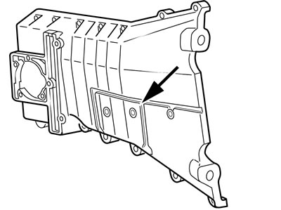
- Remove the screw plug (arrow) for the chain tensioner in the timing case cover.
Note: Turn the camshaft in the direction of rotation or press until the oil is forced out of the chain tensioner and the pin for the chain tensioner can be pushed in as far as the stop.
- Insert chain tensioner pin, BMW No. 11 6 740, in timing case cover to locate the chain tensioner.
Caution: Position the pistons midway up the cylinders (cylinder 1 approx. 90° before top dead centre), to avoid damage to the valves and pistons.
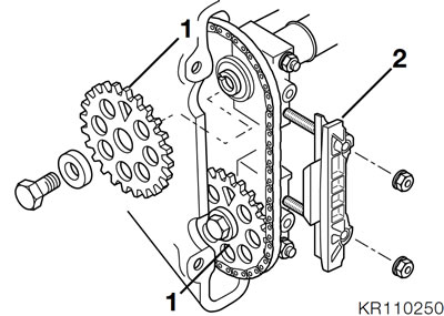
- Release slide rail (2).
- Release the chain sprockets (1), holding the hexagon on the camshaft to prevent it from turning.
Note: The timing chain must not come away from the crankshaft pinion, secure it to the chain sprockets with a cable tie.
- Remove the chain sprockets and slide rail.
- Turn the camshafts until the tips of the cams are clear.
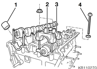
- Remove the bearing caps (2) for the thrust bearings first, to prevent tilting.
- Uniformly release studs of radial bearing caps (3) and remove the bearing caps.
- Take out the camshafts.
- Use a rubber extractor, BMW No. 113251, to withdraw the bucket tappets from the cylinder head.
- Oil the replacement tappets lightly and insert.
- Oil the camshaft bearing journals.
Identification marks, camshafts
- Inlet — 2 grooves behind the thrust bearing
- Exhaust — 1 groove behind the thrust bearing
Identification marks, camshaft bearing caps
- Inlet side — odd numbers
- Exhaust side — even numbers
Consecutive numerical order from front (timing end) to rear.
- Insert the camshafts in such a way that the tips of the cams are clear.
- Install the inner bearing caps first.
- Install the thrust bearing (timing end) with slide rail last and do not tighten it until the chain sprockets have been installed.
- Tighten the bearing caps uniformly, working from the inside outwards.
Tightening torque:
- Bearing cap — 10 Nm
- Turn the camshafts so that the grooves at the rear (opposite end from timing end) are vertical in relation to the cylinder head.
- The grooves at the timing end must face towards the crankshaft.
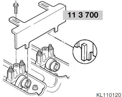
- Attach the aligning device, BMW No. 11 3 700, and secure to camshaft bearing caps.
Caution: When turning the crankshaft, make sure that the timing chain does not come away from the crankshaft sprocket.
- Turn crankshaft by a further 90°, note the direction of rotation, piston of cylinder 1 must be at top dead centre.
- Install the inlet camshaft chain sprocket so that the timing chain is taut at the guide rail.
- Insert the screw as far as possible.
- Install the exhaust camshaft chain sprocket so that the timing chain is as taut as possible between the sprockets (in the slide rail).
- Insert the screw as far as possible.
- Remove the aligning device, BMW No. 11 3 700.
- Push the camshaft lightly against the thrust bearing and fasten the bearing cover with the sliding rail.
- Tighten the chain sprockets, holding the hexagon on the camshaft to prevent it from turning.
- Remove the chain tensioner clamping tool and tighten the screw plug.
Tightening torques:
- Bearing cap — 10 Nm
- Chain sprockets — 56 Nm
- Timing case cover — 9 Nm
- Screw plug for chain tensioner — 9
Turn the engine over and check the relative positions of the camshaft chain sprockets and the crankshaft (at TDC).
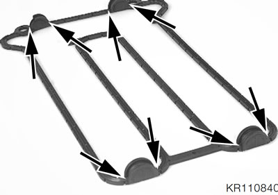
- Install the cylinder head cover gasket with the half-moon cutouts first. The marks at the front and rear of the gasket and the cylinder head cover must coincide.
- Apply a thin coat of Three Bond 1209 at the areas where the cylinder head, timing case cover and cylinder head cover meet and at the halfmoon cutouts (arrows).
Note: Do not forget the contact spring.
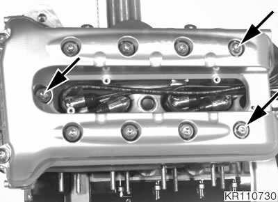
- Install the cylinder head cover. Insert the front centre screw (timing end, arrow) and both rear screws (arrows) in order to locate the gasket.
- Tighten all screws until seated.
- Tighten the screws in diagonally opposite sequence, working from the inside outwards.
- Install the cover plate.
Tightening torques:
- Cylinder head cover — 9 Nm
- Spark plugs — 20 Nm
- Cover plate screws — 5 Nm
Install the skirt bracket, engine spoiler and left fairing section.
Tightening torques:
- Skirt bracket — 21 Nm
Replacing the chain tensioning rail lining and chain guide rail (every 60,000 km/36,000 miles)
See Group 11.