
Bulb replacement except XL 1200C/C ANV/CP/CA/CB
| FASTENER | TORQUE VALUE | |
| Tail lamp lens screw | 20-24 in·lbs | 2.3-2.7 Nm |
Note. XL 883N/XL 1200X/V:
- The stop lamps are dual filament turn signal bulbs in housings with red lenses. Replace the turn signal bulbs.
- Certain markets require the XL 883R/L tail lamp.
1. Turn the ignition switch to OFF.
2. See Figure 6-44. Remove two screws and lens (4) from base (3).
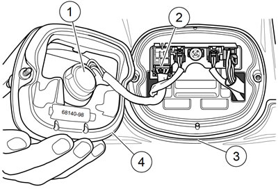
Figure 6-44. Tail lamp: 1. Bulb/socket assembly; 2. 4-pin multilock connector; 3. Base; 4. Lens
3. Press the locking tab. Remove 4-pin multilock connector from circuit board.
4. Turn socket assembly (1) one-quarter turn counterclockwise to release assembly from lens. Remove (pull) assembly from lens. Remove bulb from socket.
5. Coat base of new bulb with ELECTRICAL CONTACT LUBRICANT. Install new bulb into socket.
6. Install bulb assembly into lens. Turn assembly one-quarter turn clockwise to lock in place.
7. Connect 4-pin multilock connector to circuit board.
8. Install lens to base with two screws. Tighten to 20-24 in·lbs (2.3-2.7 Nm).
Warning! Be sure that all lights and switches operate properly before operating motorcycle. Low visibility of rider can result in death or serious injury.
9. Test tail lamp.
Base replacement: XL 883R/L AND XR 1200X
| FASTENER | TORQUE VALUE | |
| Tail lamp base mounting screw: XL Models | 45-48 in·lbs | 5.1-5.4 Nm |
| Tail lamp base mounting screw: XR 1200X | 36-60 in·lbs | 4.1-6.8 Nm |
| Tail lamp lens screw | 20-24 in·lbs | 2.3-2.7 Nm |
Warning! To prevent accidental vehicle start-up, which could cause death or serious injury, remove main fuse before proceeding.
1. Remove main fuse.
2. See Figure 6-45 or Figure 6-46. Remove two screws (1) and lens (2) from base (9).
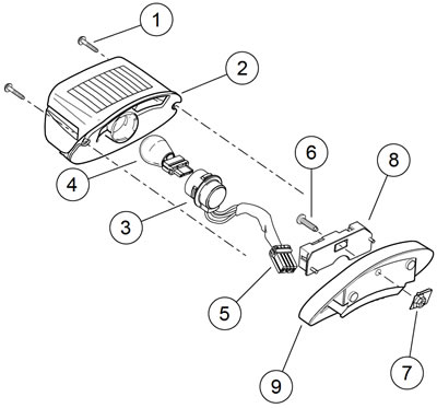
Figure 6-45. Tail lamp assembly: XL 883R/L: 1. Screw; 2. Lens; 3. Socket; 4. Bulb; 5. Tail lamp connector [93]; 6. Screw; 7. Nut plate; 8. Circuit board; 9. Base
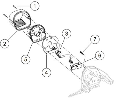
Figure 6-46. Tail lamp assembly: XR 1200X: 1. Screw; 2. Lens; 3. Socket; 4. Gasket; 5. Reflector; 6. Circuit board; 7. Fastener
3. See Figure 6-47. Press locking tab and remove 4-Pin multilock connector [93] (1) from circuit board.
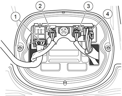
Figure 6-47. Tail lamp base connectors: 1. Tail lamp [93]; 2. Left turn signal [19]; 3. Right turn signal [18]; 4. Power in [94]
4. Press locking tabs and remove right [18] (3) and left [19] (2) two 2-Pin turn signal connectors and 6-Pin Power In connector [94] (4) from the circuit board.
5. XL Models except 1200C/CP/CA/CB: See Figure 6-45. Remove base as follows:
- a. Remove screw (6) from nut plate (7).
- b. Remove circuit board (8) from base.
- c. Remove base (9) from rear fender.
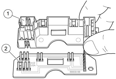
Figure 6-48. Pin housing and circuit board: 1. Pin housing; 2. Circuit board
6. XL Models except 1200C/CP/CA/CB: Install base as follows:
- a. Install base on rear fender.
- b. Install screw, pin housing and circuit board to base. Tighten to 45-48 in·lbs (5.1-5.4 Nm).
7. XR 1200X: See Figure 6-49. Remove base as follows:
- a. Remove pin housing and circuit board from base.
- b. Remove screws (1, 2) and remove base from frame.
- c. If replacing base, remove turn signals from base. See 6.18 FRONT TURN SIGNALS.
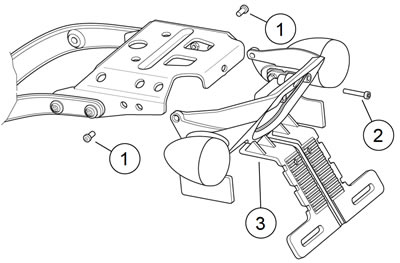
Figure 6-49. Tail lamp base: XR 1200X: 1. Screw (2); 2. Screw; 3. Base
8. XR 1200X: See Figure 6-49. Install base as follows:
- a. Install base to frame with screws (1, 2). Tighten screw to 36-60 in·lbs (4.1-6.8 Nm).
- b. Set pin housing and circuit board onto base.
9. Install connectors to circuit board.
10. Install lens to base with two screws. Tighten screws to 20-24 in·lbs (2.3-2.7 Nm).
11. Install main fuse.
Warning! Be sure headlamp, tail and stop lamp and turn signals are operating properly before riding. Poor visibility of rider to other motorists can result in death or serious injury.
12. Verify operation of lighting system.
LED tail lamp: XL 1200C/C ANV/CP/CA/CB
| FASTENER | TORQUE VALUE | |
| Tail lamp LED screws: XL 1200C/C ANV/CP/CA/CB | 20-25 in·lbs | 2.3-2.8 Nm |
| Tail lamp LED base fasteners: XL 1200C/C ANV/CP/CA/CB | 40-50 in·lbs | 4.5-5.6 Nm |
Removal
Warning! To prevent accidental vehicle start-up, which could cause death or serious injury, remove main fuse before proceeding.
1. Remove main fuse.
2. Remove the seat.
3. See Figure 6-50. Separate the tail lamp subharness connector [40] housings.
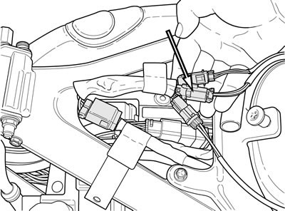
Figure 6-50. Tail lamp subharness connector [40]
4. Remove the lower rear shock bolts and raise the motorcycle to access the tail lamp. See 2.24 SHOCK ABSORBERS.
5. See Figure 6-51. Remove the fasteners (3) and remove the wire harness from the inner fender rail.

Figure 6-51. LED tail lamp: XL 1200C/C ANV/CP/CA/CB: 1. LED tail lamp; 2. Base; 3. Fasteners; 4. Screws; 5. Gasket; 6. Subharness connector [40]
6. Separate the tail lamp base (2) from the rubber gasket (5).
7. Remove the two screws (4) to remove the LED (1) from the tail lamp base.
Installation
1. Thread the LED wire harness through the tail lamp base and the rubber gasket.
2. Fasten the LED to the tail lamp base and tighten the screws to 20-25 in·lbs (2.3-2.8 Nm).
3. Loosely install the rubber gasket and the tail lamp to the fender and thread the wire harness back through the inner rail.
4. Tighten the fasteners to 40-50 in·lbs (4.5-5.6 Nm).
5. Lower the rear wheel and install the shock bolts. See 2.24 SHOCK ABSORBERS.
6. Connect the subharness connector [7] housings.
7. Install main fuse.
Warning! After installing seat, pull upward on seat to be sure it is locked in position. While riding, a loose seat can shift causing loss of control, which could result in death or serious injury.
8. Install the seat.
Warning! Be sure that all lights and switches operate properly before operating motorcycle. Low visibility of rider can result in death or serious injury.
9. Verify operation of lighting system.