
Note. This part cannot be repaired. Replace upon failure.
Preliminary disassembly: all models
Warning! To prevent spray of fuel, purge system of high-pressure fuel before supply line is disconnected. Gasoline is extremely flammable and highly explosive, which could result in death or serious injury.
1. Position vehicle upright. Purge the fuel supply hose of high pressure gasoline. Disconnect fuel supply hose from fuel pump module. See 4.4 FUEL TANK: XL MODELS or 4.5 FUEL TANK: XR 1200X.
Warning! To prevent accidental vehicle start-up, which could cause death or serious injury, remove main fuse before proceeding.
2. Remove main fuse.
3. Remove seat.
4. Remove fuel tank. See 4.4 FUEL TANK: XL MODELS or 4.5 FUEL TANK: XR 1200X.
5. See 6.28 ELECTRICAL CADDIES:
- a. XL Models: Remove screw securing left wire harness caddy to right wire harness caddy.
- b. Locate instruments connector [20] on right wire harness caddy for XL models and on left side of caddy for XR 1200X. Unplug connector [20A].
6. Record the location of all cable straps securing instrument harness to vehicle. Cut cable straps to free instrument harness.
Replacement: XL 1200C/C ANV/CP/CA except with mini-ape handlebar
| FASTENER | TORQUE VALUE | |
| Handlebar riser clamp screw | 12-18 ft·lbs | 16.3-24.4 Nm |
| Handlebar riser clamp screw | 12-18 ft·lbs | 16.3-24.4 Nm |
| Handlebar riser cover screw | 8-12 in·lbs | 0.9-1.4 Nm |
1. See Figure 6-41. Remove two screws (1) and riser cover (2) from behind handlebar riser (3).
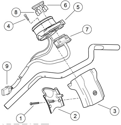
Figure 6-41. Indicator lamps: XL 1200C/C ANV/CP/CA Except w/mini-ape handlebar: 1. Screw (2); 2. Riser cover; 3. Handlebar riser; 4. Screw (4); 5. Speedometer housing/handlebar clamp; 6. Indicator lamp bezel with lens; 7. Indicator lamp module; 8. Latch (4); 9. Instrument harness connector [20A]
2. Remove four screws (4) securing speedometer housing/handlebar clamp (5) to handlebar riser.
3. Carefully bend back four latches (8) on indicator lamp bezel (6). Remove indicator lamp module (7).
4. Remove the speedometer. See 6.4 SPEEDOMETER: XL MODELS, Removal.
5. Carefully pull harness with connector [39B] and trip odometer reset button from back of speedometer housing/handlebar clamp.
6. Pull instrument harness with connector [20A] up through upper fork bracket and remove harness from vehicle.
7. Place new instrument harness in position.
8. Carefully feed connector [20A] end down through upper fork bracket and along left side of frame steering head.
Note. Verify that speedometer harness and trip odometer switch harness are positioned underneath the handlebar and that the indicator lamp module harness feeds over the top of the handlebar.
9. Carefully feed end of harness with connector [39B] and trip odometer reset button through back of speedometer housing/handlebar clamp.
10. Install the speedometer. See 6.4 SPEEDOMETER: XL MODELS, Installation.
11. See Figure 6-41. Install indicator lamp module (7) into back of speedometer housing/handlebar clamp (5). Secure with four latches (8) on indicator lamp bezel (6).
12. Install speedometer housing/handlebar clamp onto handlebar riser (3). Secure with four screws (4).
13. Adjust the handlebar to the desired position.
14. Tighten:
- a. Front screws first, to 12-18 ft·lbs (16.3 -24.4 Nm).
- b. Rear screws to 12-18 ft·lbs (16.3 -24.4 Nm).
15. Install riser cover (2) behind handlebar riser. Secure with two screws (1). Verify that the handlebar control harnesses are not pinched between handlebar riser and riser cover. Tighten to 8-12 in·lbs (0.9-1.4 Nm).
16. Proceed to 6.15 INDICATOR LAMP MODULE, Assembly: All Models.
Replacement: XL 883R/L/N, XL 1200X/V, XL 1200CP/CB with mini-ape handlebar
| FASTENER | TORQUE VALUE | |
| Handlebar clamp screw | 12-18 ft·lbs | 16.3-24.4 Nm |
| Handlebar clamp screw | 12-18 ft·lbs | 16.3-24.4 Nm |
1. Cover headlamp bracket with a clean soft cloth to protect surface.
2. See Figure 6-42. Holding speedometer housing/handlebar clamp (2), remove four screws securing housing/clamp assembly to handlebar risers.
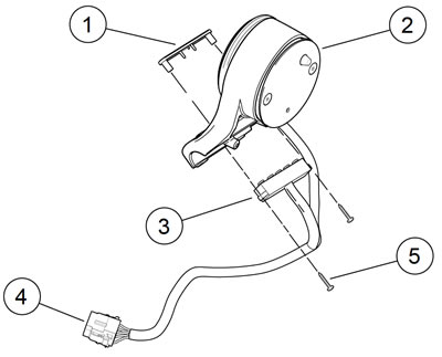
Figure 6-42. Indicator lamps: XL 883R/L/N, XL 1200X/V, XL 1200CP/CB (w/mini-ape handlebar): 1. Indicator lamp bezel; 2. Speedometer housing/handlebar clamp; 3. Indicator lamp module; 4. Instrument harness connector [20A]; 5. Screw (2)
3. Remove two screws (5) to separate indicator lamp module (3) from speedometer housing/handlebar clamp and the indicator lamp bezel.
4. Remove speedometer. See 6.4 SPEEDOMETER: XL MODELS, Removal.
5. Remove instrument harness.
6. Place new instrument harness in position.
7. Install speedometer. See 6.4 SPEEDOMETER: XL MODELS, Installation.
8. See Figure 6-42. Assemble the indicator lamp bezel (1) and the indicator lamp module (3) onto speedometer housing/handlebar clamp (2). Secure with two screws (5).
9. Install housing/clamp assembly onto handlebar risers. Secure with screws:
10. Tighten:
- a. Rear screws first, to 12-18 ft·lbs (16.3-24.4 Nm).
- b. Front screws to 12-18 ft·lbs (16.3-24.4 Nm).
11. Proceed to 6.15 INDICATOR LAMP MODULE, Assembly: All Models.
Replacement: XR 1200X
| FASTENER | TORQUE VALUE | |
| Handlebar clamp screw | 12-18 ft·lbs | 16.3-24.4 Nm |
1. Cover headlamp bracket with a clean soft cloth to protect surface.
2. See Figure 6-43. Holding instrument bracket (2), remove two screws with lockwashers securing instrument bracket to handlebar risers.
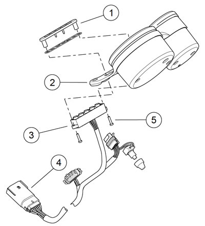
Figure 6-43. Indicator lamps: XR 1200X: 1. Indicator lamp bezel; 2. Instrument bracket; 3. Indicator lamp module; 4. Instrument harness connector [20A]; 5. Screw (2)
3. Remove two screws (5) to separate indicator lamp module (3) from instrument bracket and the indicator lamp bezel (1).
4. Remove instrument harness. See 6.4 SPEEDOMETER: XL MODELS or 6.5 SPEEDOMETER AND TACHOMETER: XR 1200X.
5. Install new instrument harness. See 6.4 SPEEDOMETER: XL MODELS or 6.5 SPEEDOMETER AND TACHOMETER: XR 1200X.
6. See Figure 6-43. Assemble the indicator lamp bezel and the indicator lamp module (3) onto instrument bracket (2). Secure with two screws (5).
7. Install instrument bracket onto handlebar risers. Tighten to 12-18 ft·lbs (16.3-24.4 Nm).
8. Proceed to 6.15 INDICATOR LAMP MODULE, Assembly: All Models.
Assembly: all models
1. XL Models: See 6.28 ELECTRICAL CADDIES.
- a. Feed instrument harness between coil bracket uprights, back to right wire harness caddy.
- b. Plug instrument harness pin connector [20A] into socket connector [20B] in right wire harness caddy.
- c. Mate right and left wire harness caddies. Secure with screw and tighten.
2. XR 1200X: See 6.28 ELECTRICAL CADDIES.
- a. Feed instrument harness along left side of frame next to left and right hand control harnesses and inside of coil bracket upright.
- b. Plug instrument harness pin connector [20A] into socket connector [20B] in right wire harness caddy.
3. Secure instrument harness to vehicle with cable straps in locations previously noted.
4. Install fuel tank. See 4.4 FUEL TANK: XL MODELS or 4.5 FUEL TANK: XR 1200X.
5. Install main fuse.
Warning! After installing seat, pull upward on seat to be sure it is locked in position. While riding, a loose seat can shift causing loss of control, which could result in death or serious injury.
6. Install seat.