
- Oxygen Sensor #1: Service Code 33
- Oxygen Sensor #2: Service Code 83
Oxygen sensor removal/installation
Refer to Oxygen sensor removal and installation in the Electrical System chapter.
Oxygen sensor inspection
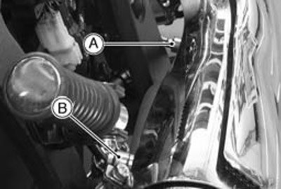
Note. The oxygen sensor itself is the same for #1 [A] and #2 [B], but wiring of the main harness side is different.
Warm up the engine thoroughly.
Turn the ignition switch OFF.
Remove the right side cover (see Right side cover removal in the Frame chapter).
Connect a digital voltmeter [A] to the each oxygen sensor connector [B] (sensor side), using the needle adapter set.
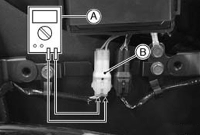
- Special Tool - Needle Adapter Set: 57001-1457
Oxygen sensor output voltage:
- Connections to oxygen sensor connector:
- Meter (+) → BK lead
- Meter (-) → GY lead
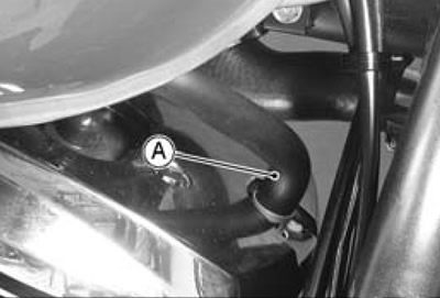
Remove the air switching valve hoses [A] (both sides) from the fittings.
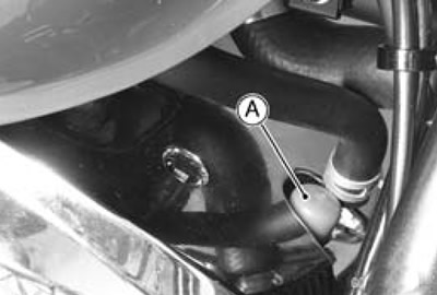
Install the suitable plugs [A] (both sides) on the fittings and shut off the secondary air.
Turn the ignition switch ON.
Start the engine, and let it idle.
Measure the output voltage of the sensor with the connector joined.
Oxygen sensor output voltage (with plugs):
- Standard: 0.45-2.5 V
Next, remove the plugs [A] (both sides) from the fittings with idling.

Measure the output voltage of the sensor with the connector joined.
Oxygen sensor output voltage (without plugs):
- Standard: 0.05-0.45 V
★ If the reading is within range (with plugs: 0.45-2.5 V, without plugs: 0.05-0.45 V), the oxygen sensor is good.
★ If the reading is without range, replace the oxygen sensor.
Remove the needle adapter set, and apply silicone sealant to the seals of the connector for waterproofing.
- Sealant - Kawasaki Bond (Silicone Sealant): 56019-120
Oxygen sensor circuit
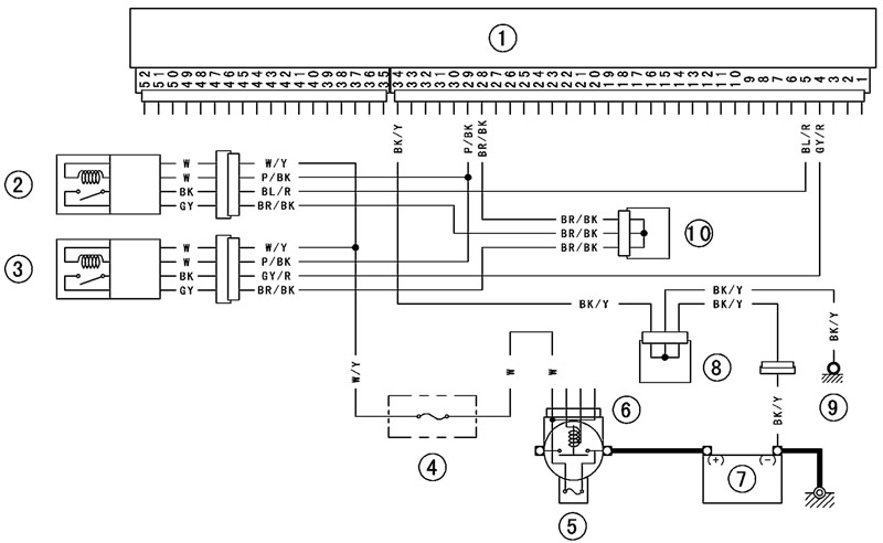
1. ECU; 2. Oxygen Sensor #1; 3. Oxygen Sensor #2; 4. Oxygen Sensor Heater Fuse 10 A; 5. Main Fuse 30 A; 6. Starter Relay; 7. Battery; 8. Joint Connector C; 9. Frame Ground; 10. Joint Connector B