Wiring diagram information
Wire Color Codes
Wire traces on wiring diagrams are labeled with alpha codes. Refer to Table B-1.
- For Solid Color Wires: See Figure B-8. The alpha code identifies wire color.
- For Striped Wires: The code is written with a slash (/) between the solid color code and the stripe code. For example, a trace labeled GN/Y is a green wire with a yellow stripe.
Wiring Diagram Symbols
See Figure B-8. On wiring diagrams and in service/repair instructions, connectors are identified by a number in brackets [ ]. The letter inside the brackets identifies whether the housing is a socket or pin housing.
- A = Pin: The letter A and the pin symbol after a connector number identifies the pin side of the terminal connectors.
- B = Socket: The letter В and the socket symbol after a connector number identifies the socket side of the terminal connectors. Other symbols found on the wiring diagrams include the following:
- Diode: The diode allows current flow in one direction only in a circuit.
- Wire break: The wire breaks are used to show option variances or page breaks.
- No Connection: Two wires crossing over each other in a wiring diagram that are shown with no splice indicating they are not connected together.
- Circuit to/from: This symbol indicates a more complete circuit diagram on another page. The symbol is also identifying the direction of current flow.
- Splice: Splices are where two or more wires are connected together along a wiring diagram. The indication of a splice only indicates that wires are spliced to that circuit. It is not the true location of the splice in the wiring harness.
- Ground: Grounds can be classified as either clean or dirty grounds. Clean grounds are identified by a (BK/GN) wire and are normally used for sensors or modules.
Note: Clean grounds usually do not have electric motors, coils or anything that may cause electrical interference on the ground circuit.
Dirty grounds are identified by a (BK) wire and are used for components that are not as sensitive to electrical interference.
- Twisted pair: This symbol indicates the two wires are twisted together in the harness. This minimizes the circuit's electromagnetic interference from external sources. If repairs are necessary to these wires they should remain as twisted wires.
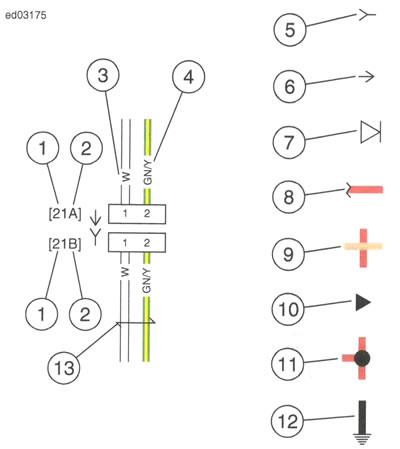
Figure B-8. Connector/Wiring Diagram Symbols: 1. Connector number; 2. Terminal code (A=pin, B=socket); 3. Solid wire color; 4. Striped wire color; 5. Socket symbol; 6. Pin symbol; 7. Diode; 8. Wire break; 9. No connection; 10. Circuit to/from; 11. Splice; 12. Ground; 13. Twisted pair
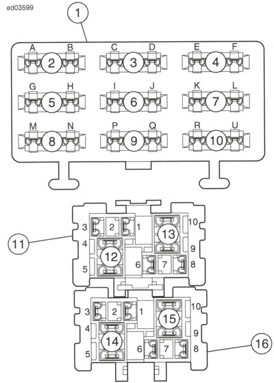
Figure B-9. Fuse Block and Socket Terminals: 1. Fuse block [64]; 2. Accessory fuse; 3. Fan fuse; 4. Ignition fuse; 5. Lights/instrument fuse; 6. Lights fuse; 7. Fuel pump fuse; 8. Open; 9. Open; 10. Battery fuse; 11. Relay block [61]; 12. Start relay; 13. Fan relay; 14. System relay; 15. Ignition relay; 16. Relay block [62]
Table B-1. Wire Color Codes
| ALPHA CODE | WIRE COLOR |
| BE | Blue |
| BK | Black |
| BN | Brown |
| GN | Green |
| GY | Gray |
| LGN | Light Green |
| 0 | Orange |
| PK | Pink |
| R | Red |
| TN | Tan |
| V | Violet |
| W | White |
| Y | Yellow |
2015 Street wiring diagrams
Refer to the table below for wiring diagram information.
Wiring Diagram List
| DIAGRAM | LOCATION |
| IGN and ACC | Figure B-10 |
| Grounds | Figure B-11 |
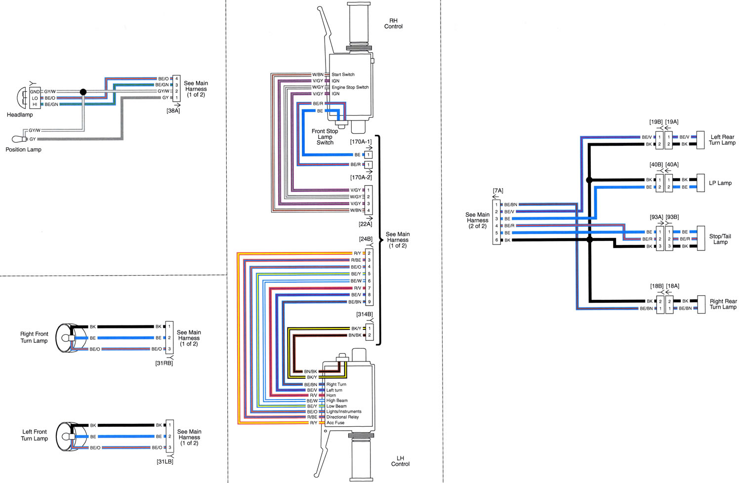
| Lighting and Hand Controls: 2015 Street | Figure B-12 |
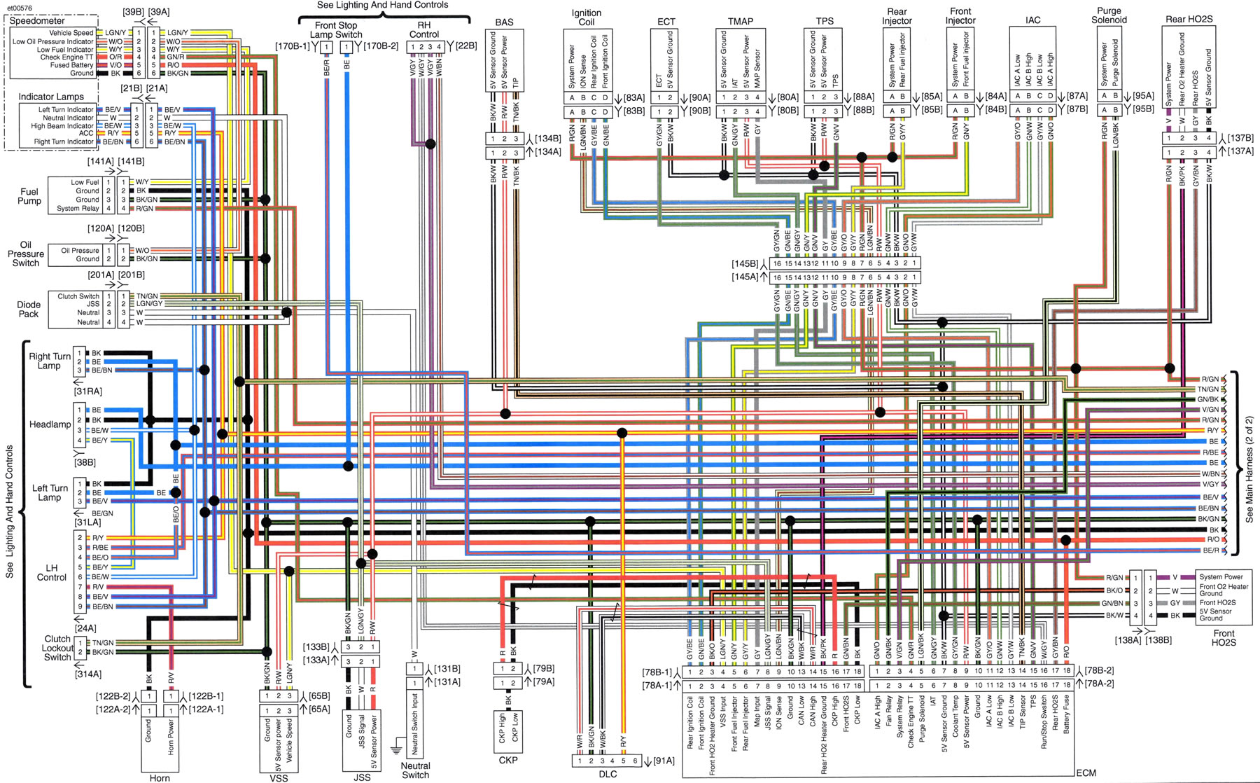
| Main Harness (1 of 2): 2015 Street | Figure B-13 |
| Main Harness (2 of 2): 2015 Street | Figure B-14 |
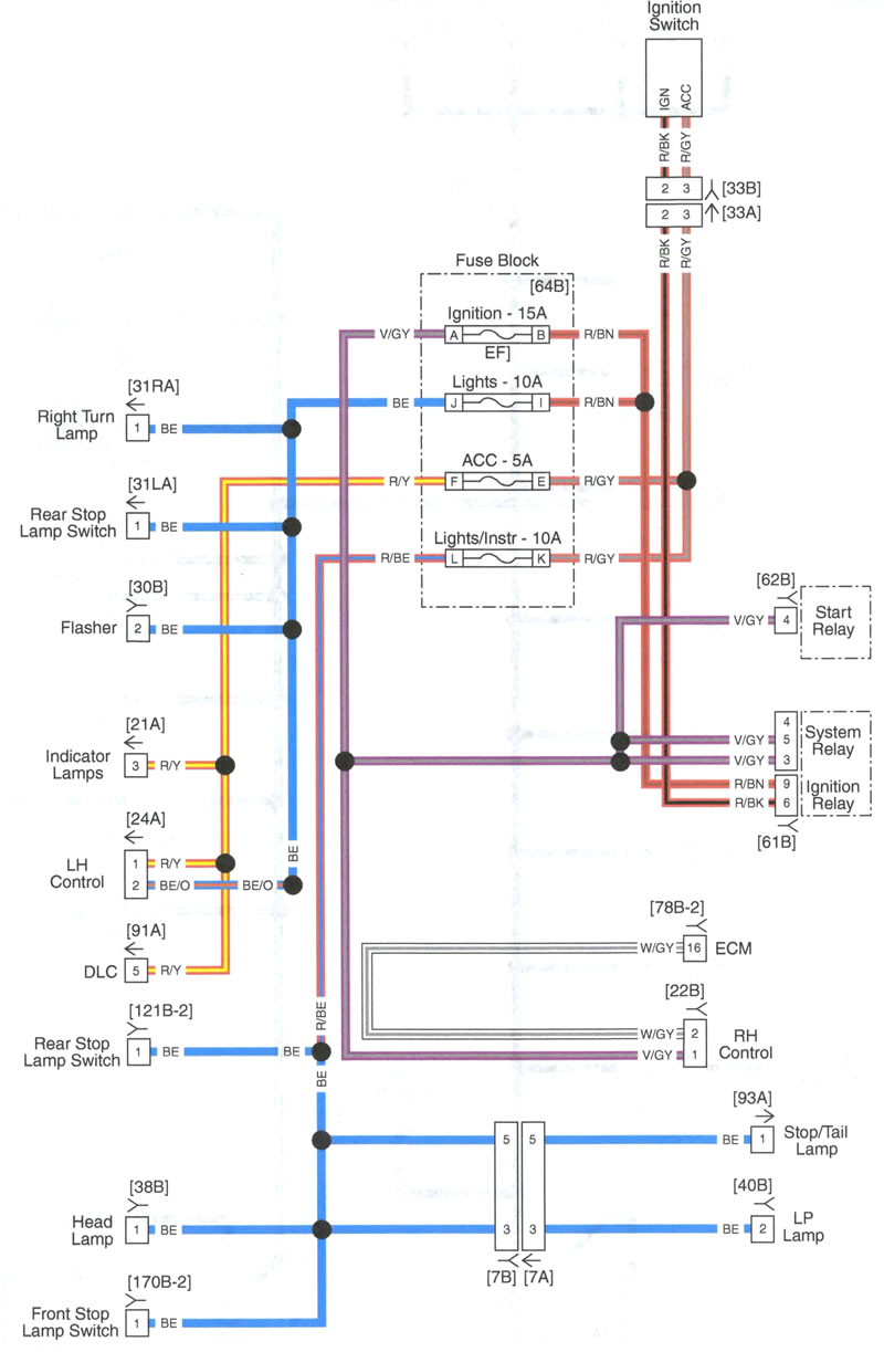
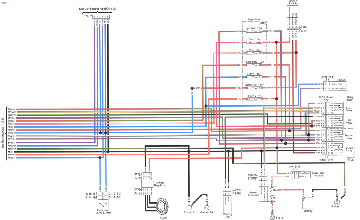
Figure B-10. IGN and ACC
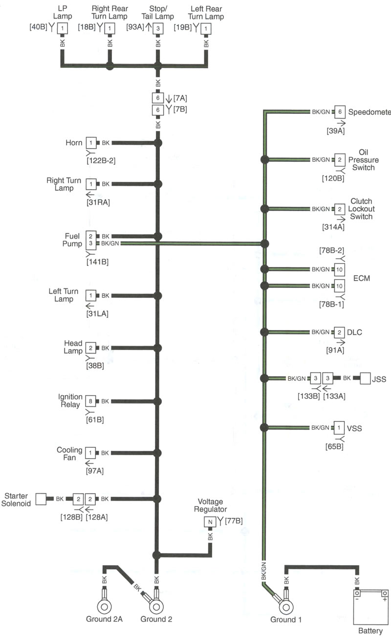
Figure B-11. Grounds

