Disconnect and connect
Disconnect
1. See Figure A-12. Press the latch.
2. Pull the connector housings apart.
Connect
1. Align the connector housings.
2. Press the housings together until the latch snaps into place.
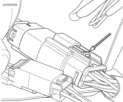
Figure A-12. Molex MX 150 Sealed Connector: Latch
Remove terminal
| PART NUMBER | TOOL NAME |
| HD-48114 | TERMINAL REMOVER |
1. Pull the secondary lock up, approximately 4.8 mm (0.2 in), until it stops.
- a. Socket housing: See Figure A-13. Use a small screwdriver in the pry slot. The slot next to the external latch provides a pivot point.
- b. Pin housing: See Figure A-14. Use needle nose pliers to engage the D-holes in the center of the secondary lock.
Note: Do not remove the secondary lock from the connector housing.
2. See Figure A-15. Insert TERMINAL REMOVER (Part No. HD-48114) into the pin hole next to the terminal until the tool bottoms.
- a. Socket housing: The pin holes are inside the terminal openings.
- b. Pin housing: The pin holes are outside the pins.
3. Remove terminal.
- a. Push terminal remover into pin hole.
- b. Gently pull on the wire to remove wire terminal from the chamber.
3. Remove terminal.
- a. Push terminal remover into pin hole.
- b. Gently pull on the wire to remove wire terminal from the chamber.
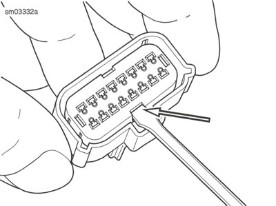
Figure A-13. Secondary Lock Pry Slot (Socket Housing)
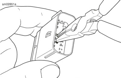
Figure A-14. Pull Up Secondary Lock
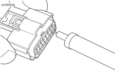
Figure A-15. Molex MX 150 Sealed Connector: Terminal Remover (HD-48114)
Install terminal
Note: See Figure A-16. Cavity numbers (1) are stamped on the housing at the ends of the cavity rows. Determine the cavity number by counting the cavities up ordown along the row from each stamped number.
1. Align terminal to the housing.
2. See Figure A-16. Install the terminal into the housing. Tang (2) engages slot (3).
3. Gently pull on wire to verify that the terminal is captured by the secondary lock.
4. Push the secondary lock into the socket housing to lock the wire terminals into the housing.
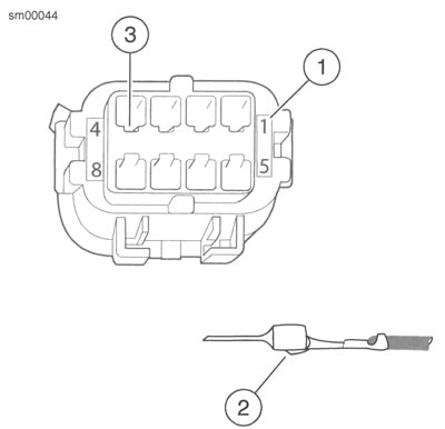
Figure A-16. Molex MX 150 Sealed Connector: Pin Cavities and Wire Terminal: 1. Cavity number; 2. Tang; 3. Cavity slot
Crimp terminal
| PART NUMBER | TOOL NAME |
| HD-48119 | TERMINAL CRIMPER |
1. Identify the punch/die in the jaws of the TERMINAL CRIMPER (Part No. HD-48119) for the wire gauge. Refer to Table A-2.
2. Open the tool.
3. See Figure A-17. Hold fully open tool at approximately 45 degrees.
Note: Do NOT tighten the locknut holding the locator bars. The bars must float to accommodate the different terminal gauges.
Table A-2. Crimp Tool Wire Gauge Punch/Die
| AWG (WIRE GAUGE) | PUNCH/DIE |
| 22 | Left |
| 18-20 | Middle |
| 14-16* | Right |
* Crimp 16 AWG pin terminals in the 18-20 middle die.
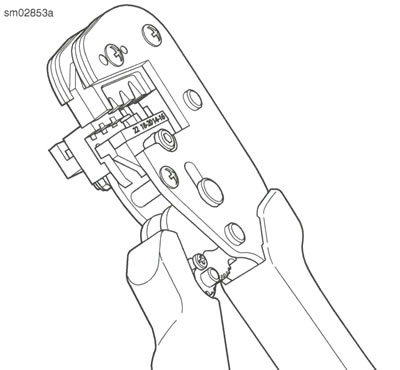
Figure A-17. Open Terminal Crimper (HD-48119) at 45 Degrees
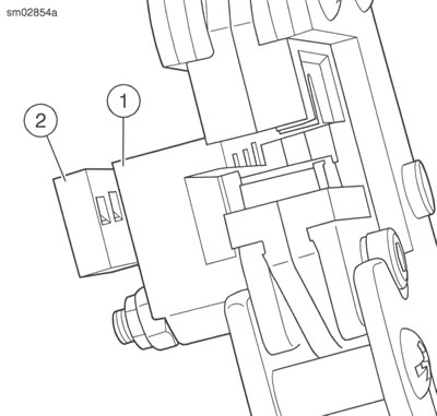
Figure A-18. Terminal Locator Bars: 1. Socket locator bar; 2. Pin locator bar
4. Remove 4.7-5.6 mm (0.2 in) of insulation from the wire lead.
5. See Figure A-19. With the crimp tails up, place the terminal through the punch/die into the square opening in the socket locator bar.
- a. Socket terminal: See Figure A-18. A socket terminal stops against the back face of the socket locator bar (1).
- b. Pin terminal: See Figure A-20. The tip of a pin terminal passes through the socket locator bar and stops in the notch in the face of the pin locator bar.
6. See Figure A-21. Ratchet the handles together until the crimp tails are held in vertical alignment between the punch and the die.
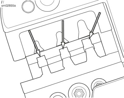
Figure A-19. Square Openings in Socket Locator Bar
See Figure A-22. Insert the wire lead between the crimp tails, angled up until the wire core touches the face of the socket locator bar above the square opening.
Notes:
- The insulation must extend through the insulation crimp tails.
- Insert the wire with little or no pressure. Pressing on the lead will bend the wire core.
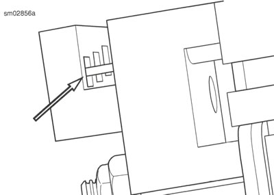
Figure A-20. Pin Terminal against Pin Locator Bar
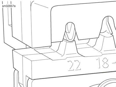
Figure A-21. Crimp Tails in Vertical Alignment between Punch and Die
7. Holding the wire lead in position touching the locator face at an angle, quickly and smoothly squeeze the crimp tool closed.
8. Squeeze the handles to open the tool and release the terminal.
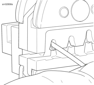
Figure A-22. Stripped Lead at Up Angle
1. Inspect crimp: Inspect the core and insulation crimp.
- a. See Figure A-23. The core tails should be creased into the wire strands at the core crimp (1).
- b. Wire strands (2) should extend beyond the core crimp but not into the terminal shell.
- c. The insulation tails should be folded into the insulation crimp (3) without piercing or cutting the insulation.
- d. Distortion should be minimal.
2. Test crimp: Hold the terminal. Pull the lead.
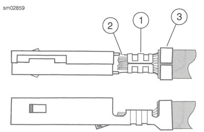
Figure A-23. Terminal Crimp: 1. Core crimp; 2. Wire strands; 3. Insulation crimp
