
General
Remove cam drive, rotor and cylinder heads. Split crankcases. Remove lower crankcase and set aside.
| PART NO. | SPECIALTY TOOL |
| HD-45316 | Crankshaft assembly retainer |
| HD-44358 | Flywheel support fixture |
| HD-45313 | Cylinder liner remover/installer |
| HD-96333-51 C | Piston ring compressor |
| HD-45306 | Crankshaft locking pin |
1. See Figure 3-189. Install CRANKSHAFT ASSEMBLY RETAINER (HD-45316).

Figure 3-189. Install crankshaft assembly retainers (HD-45316)
2. See Figure 3-190. Note the casting bumps on the connecting rods and caps. The rear cylinder must have the bumps toward the water pump side and the front cylinder toward the cam drive side.

Figure 3-190. Connecting rod orientation
3. See Figure 3-191. Note the numbers on connecting rod and cap. Connecting rods and caps must be used in matched sets.
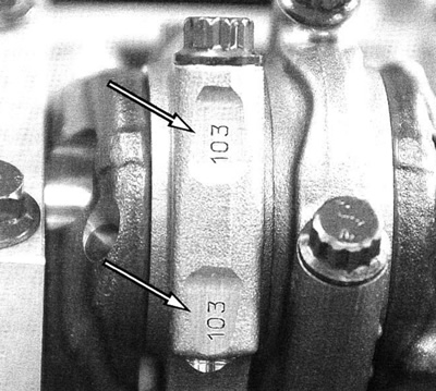
Figure 3-191. Match rod and cap
4. See Figure 3-192. Loosen connecting rod caps fasteners.
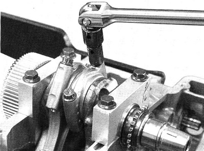
Figure 3-192. Loosen rod cap fasteners
5. Remove the CRANKSHAFT ASSEMBLY RETAINERS (HD-45316).
6. See Figure 3-193. Inspect connecting rod bearing shells. Look for scoring or discoloration.
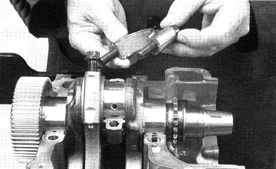
Figure 3-193. Remove rod caps
7. See Figure 3-194. Remove crankshaft.

Figure 3-194. Remove crankshaft
8. See Figure 3-195. Check journals for scoring, bluing and surface damage. Check main drive gear for wear or missing teeth.
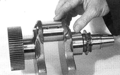
Figure 3-195. Inspect crankshaft
Note. Mild bluing around crankshaft journal and sprocket edges is due to heat treating process and is normal. However, metal transfer and bluing on journal surface indicates damage and crankshaft must be replaced.
9. See Figure 3-196. Measure crankshaft journals. For crankshaft bearing selection see Table 3-33.

Figure 3-196. Measure journal
10. See Figure 3-197. Remove crankshaft main bearing retainers.

Figure 3-197. Remove main bearing retainers
11. See Figure 3-198. If rods are to be reused, mark them F (front) and R (rear). Rod must be installed in the same position.
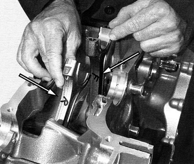
Figure 3-198. Mark connecting rods
12. See Figure 3-199. Inspect bearing shells for scoring or discoloration.
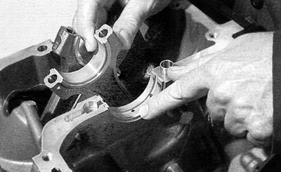
Figure 3-199. Bearing shells
13. See Figure 3-200. Carefully push piston and rod out top of cylinder. Avoid contacting piston jet. Do not let the connecting rod contact the cylinder liner wall.
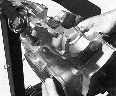
Figure 3-200. Remove pistons
Warning! Always wear proper eye protection when removing retaining rings. Slippage may propel the ring with enough force to cause eye injury.
14. See Figure 3-201. Remove and discard wrist pin retaining rings. Place small screwdriver under end and twist.

Figure 3-201. Wrist pin retaining rings
15. See Figure 3-202. Note rod and cap identifying numbers and casting bumps. Install rod caps and tighten to 27 Nm (20 ft-lbs). Position the Torque Angle Gauge (Snap-on Part No. TA360) per instruction sheet and tighten connecting rod bolts an additional 90°.

Figure 3-202. Install rod caps for inspection
Note. The notation for this torque sequence is written: 27 Nm + 90°
16. See Figure 3-203. Check big end dimensions with a dial bore gauge. Measurement must be between a maximum of 51.616 mm (2.032 in.) and a minimum of 51.60 mm (2.031 in.).
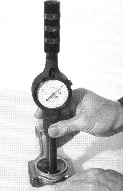
Figure 3-203. Measure big end
17. See Figure 3-204. Inspect small end bushing and wrist pin fit. The running clearance should be between a maximum of 0.033 mm (0.001 in.) and a minimum of 0.018 mm (0.0007 in.).
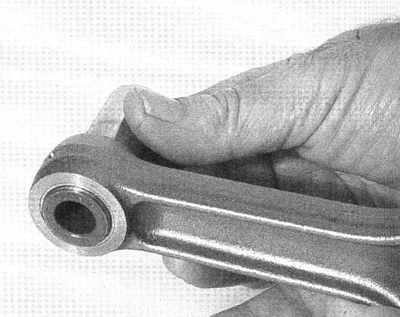
Figure 3-204. Inspect small end
18. Match replacement pistons to replacement liners. See Table 3-19.
Table 3-31. Piston to cylinder liner
| Liner | Piston |
| Class I | Class I or Class X |
| Class II | Class II or Class X |
19. See Figure 3-205. Measure piston diameter on thrust surface. Measurement should be between a maximum of 99.961 mm (3.9354 in.) and a minimum of 99.953 mm (3.9351 in.) at the largest point of the piston thrust surface.
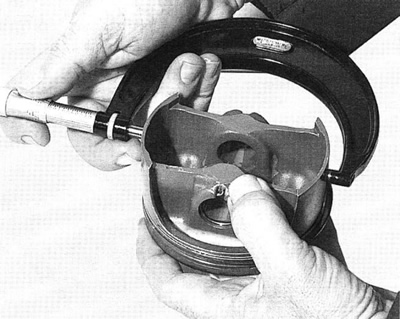
Figure 3-205. Piston measurement
Note. Piston size could vary 0.0076 mm (0.0003 in.) depending on class of piston.
20. See Figure 3-206. EX on piston top goes toward the exhaust valves. Front piston EX will go toward the front of the engine. Rear piston EX will go toward the rear of the engine.
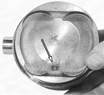
Figure 3-206. Piston orientation mark
21. See Figure 3-208. Remove and discard primary drive gear fasteners.

Figure 3-208. Remove primary gear
22. See Figure 3-207. FLYWHEEL SUPPORT FIXTURE (HD-44358) can be modified to hold Revolution crankshaft when removing or installing primary drive gear. Open bore of center hole to 59.7 mm (2.350 in.).
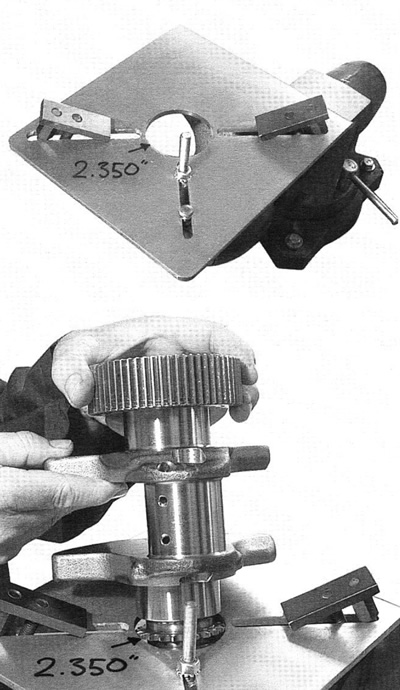
Figure 3-207. Flywheel support fixture
23. See Figure 3-209. Examine primary drive gear. Inspect thrust surfaces for excessive wear or chipping. Note the timing marks on the primary drive gear and the crankshaft. Assemble with the timing mark on the drive gear over the timing mark on the crankshaft.
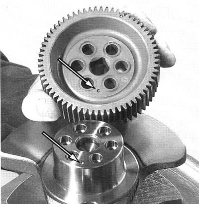
Figure 3-209. Primary gear timing marks
24. See Figure 3-210. Lubricate new primary drive gear fasteners with Harley-Davidson Motorcycle Oil 20W50. Lubricate threads and under head of bolt.

Figure 3-210. Installing primary gear
25. See Figure 3-211. Using a crisscross pattern, tighten the primary gear fasteners to 10 Nm (88 in-lbs). Position the Torque Angle Gauge (Snap-on Part No. TA360) per instruction sheet and tighten bolt an additional 90°.

Figure 3-211. Tighten primary gear
26. See Figure 3-212. Using a dial bore gauge, check cylinder concentricity. See specifications for serviceability.
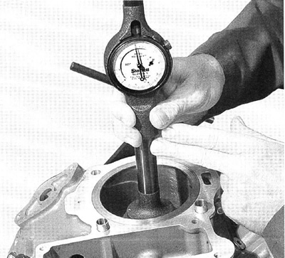
Figure 3-212. Measure cylinder bore
27. See Figure 3-213. Install CYLINDER LINER REMOVER/ INSTALLER (HD-45313) according to instruction sheet and remove liner.

Figure 3-213. Remove cylinder liner
28. See Figure 3-214. Inspect piston jet. Piston jet must fit tight and have no visible damage. If loose or damaged crankcase must be replaced.

Figure 3-214. Piston jet
29. See Figure 3-215. Carefully clean cylinder liner and step in case. Debris in the step could prevent the cylinder liner from fully seating.

Figure 3-215. Clean liner and case step
30. See Figure 3-216. Lubricate о-rings with Harley-Davidson Motorcycle Oil 20W50.
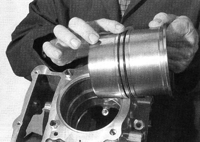
Figure 3-216. Lubricate liner
31. See Figure 3-217. Insert liner in the case bore. Install CYLINDER LINER REMOVER/INSTALLER (HD-45313) according to instruction sheet and install liner.
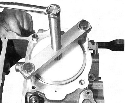
Figure 3-217. Insert liner
32. See Figure 3-218. Check ring end gap by placing ring in cylinder and measure gap using feeler gauges. See specifications for serviceability.

Figure 3-218. Ring end gap
33. See Figure 3-219. Carefully install piston rings. Second compression ring is installed with the mark to the top. When ring set is installed, gaps must be staggered.

Figure 3-219. Second compression ring top mark
34. If engine is to be assembled at this point, make sure all part are cleaned and lubricated appropriately.
Warning! Always wear proper eye protection when removing/ installing retaining rings. Slippage may propel the ring with enough force to cause eye injury.
35. See Figure 3-220. Install wrist pin and wrist pin retaining rings.
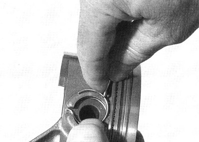
Figure 3-220. Wrist pins and retaining rings
36. See Figure 3-222. To install piston, complete each of the following steps:
- a. Lightly lubricate inside of PISTON RING COMPRESSOR (HD-96333-51 C) and rings and piston skirt with Harley-Davidson Motorcycle Oil 20W50.
- b. See Figure 3-221. Orient the brackets on the compressor ring down (Note arrow on compression ring) toward the crankcase. Orient the squeeze handle parallel to crankcase.

Figure 3-222. Insert piston

Figure 3-221. Piston ring compressor
Caution! Failure to install pistons correctly oriented will result in engine failure.
- c. Orient piston and connecting rod to crankcase.
Important note: Correct piston and connecting rod orientation is as follows:
- Front cylinder connecting rod and cap bumps to cam drive side of engine
- Rear cylinder connecting rod and cap bumps to water pump side of engine
- EX mark toward the front on front cylinder
- EX mark toward the rear on rear cylinder
- d. Clamp the PISTON RING COMPRESSOR (HD-96333-51 C) around rings and pistons.
- e. Adjust tension on handle to compress rings but still allow piston and rings to slip out of compressor into cylinder bore.
Caution! If piston jet is damaged, crankcase will have to be replaced.
- f. See Figure 3-214. With free hand inside crankcase, guide rod past piston jet.
Caution! Whenever resistance is encountered, stop and examine components. A ring can gouge the cylinder wall when forced.
- g. See Figure 3-222. Using a rubber or wooden mallet handle, very gently tap piston around circumference into bore. Hold constant pressure on the piston ring compressor until rings have entered bore.
- h. When piston and rings are in the bore, move piston up and down the bore to insure rings have not broken during installation.
37. Invert engine. Clean connecting rod bore and crank bore making sure its free of oil.
38. See Figure 3-226. Select rod bearing replacement set to match rod bearing journal diameter color code (3) on crankshaft. See Table 3-32.
Note. Rod bearing sets (front and rear) are available in two sizes, coded red (R) and blue (B). The rod bearing color code appears on the bearing shell edge.
Table 3-32. Rod bearing journal diameter
| COLOR CODE | H-D PART NO. | SPECIFICATION | |
| Red | 24412-01К | Max | 47.991 mm |
| Min | 47.983 mm | ||
| Blue | 24413-01К | Max | 47.983 mm |
| Min | 47.975 mm | ||
39. See Figure 3-223. Install rod bearings and lubricate bearing surface with Harley-Davidson Motorcycle Oil 20W50. In addition, a thin film of Lubriplate No. 105 Motor Assembly Grease (NAPA Part No. 765-2651) is recommended.

Figure 3-223. Lubricate bearings
40. See Figure 3-224. Install main bearing retainer. Use a small amount of grease on the back of the retainer to hold in position.
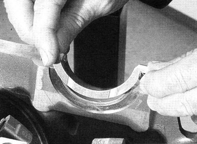
Figure 3-224. Install main bearing retainer
41. See Figure 3-225. Move connecting rods so front connecting rod points to rear, and rear rod points to front of engine.

Figure 3-225. Position connecting rods
42. See Figure 3-226. Crankshaft counter weight is stamped with a color code for main bearing and rod journal replacement sets. Read from left to right, the letter code corresponds to the alternator and clutch side main bearing journals (2) and the front rod and rear rod journals (3).

Figure 3-226. Crankshaft color code: 1. ALT (alternator side); 2. G (green main bearing code); 3. R (red rod bearing code)
43. See Table 3-33. Select main bearing set corresponding to color code (2) on crankshaft.
Table 3-33. Main bearing journal diameter
| COLOR CODE | H-D PART NO. | ALTERNATOR SIDE | CLUTCH SIDE | |
| Blue | 24411-01К | Max | 55.977 mm | 55.952 mm |
| Min | 55.971 mm | 55.946 mm | ||
| Green | 24410-01К | Max | 55.984 mm | 55.959 mm |
| Min | 55.977 mm | 55.952 mm | ||
| Red | 24409-01К | Max | 55.990 mm | 55.965 mm |
| Min | 55.984 mm | 55.959 mm |
Note. Main bearings are available in 3 sets (alternator and clutch side bearings) to fit three sizes of journals. The sets are color coded, blue (B), green (G) and red (Ft).
44. See Figure 3-227. Install crankshaft bearings and lubricate bearing surface with Harley-Davidson Motorcycle Oil 20W50. In addition, a thin film of Lubriplate No. 105 Motor Assembly Grease (NAPA Part No. 765-2651) is recommended.
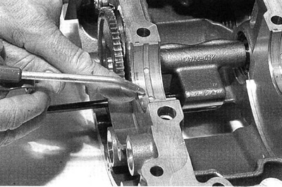
Figure 3-227. Lubricate crankshaft bearings
45. See Figure 3-228. Carefully position crankshaft.
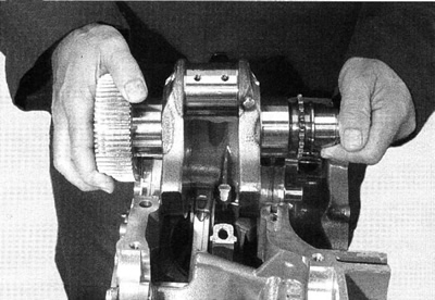
Figure 3-228. Install crankshaft
46. See Figure 3-189. When crankshaft is in position Install CRANKSHAFT ASSEMBLY RETAINER (HD-45316).
47. See Figure 3-229. Pull piston and rod assembly up to crankshaft journal.

Figure 3-229. Position connecting rods
48. See Figure 3-230. Lubricate crankshaft journal, connecting rod cap bearings, connecting rod bolt threads and under head of rod cap bolt with Harley-Davidson Motorcycle Oil 20W50. In addition, a thin film of Lubriplate No. 105 Motor Assembly Grease (NAPA Part No. 765-2651) is recommended for the rod bearings.

Figure 3-230. Lubricate crankshaft and rods
49. See Figure 3-231. Install connecting rod caps. Confirm connecting rods and caps have identical numbers and cast bumps are oriented correctly.
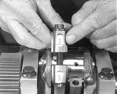
Figure 3-231. Install Connecting rod caps
- a. Front cylinder connecting rod and cap bumps to cam drive side of engine.
- b. Rear cylinder connecting rod and cap bumps to water pump side of engine.
50. See Figure 3-232.Tighten connecting rod caps to 27 Nm (20 ft-lbs).

Figure 3-232. Install connecting rod caps
51. See Figure 3-233. Position the Torque Angle Gauge (Snap-on Part No. TA360) per instruction sheet and tighten connecting rod bolts an additional 90°.
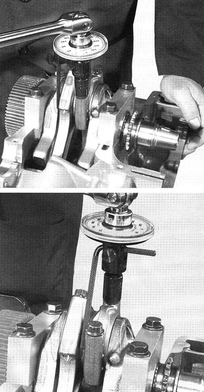
Figure 3-233. Tighten connecting rod caps
Note. The notation for this torque sequence is written: 27 Nm + 90°.
Caution! DO NOT ROTATE ENGINE CLOCKWISE. This is opposite the normal engine operation. Engine damage may result.
52. When all rod bolts are correctly torqued, turn engine to TDC and insert CRANKSHAFT LOCKING PIN (HD-45306).
53. Continue with appropriate steps under 3.14 Upper and lower crankcase service.