Note. For reasons of clarity, the figures show the engine block removed from the frame.
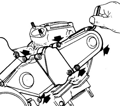
Unscrew the retaining screws on the timing belt covers and remove the covers.

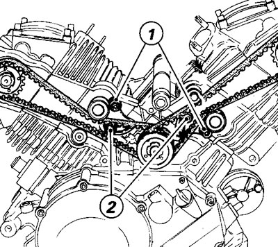
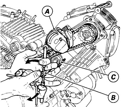
Loosing the lock screws (1) on the mobile tensioners and fit the service gauge (A, code no. 051.2.001.1A) on the upper belt.

Fit the special tool (B, code no. 88713.1215) on the pivot screw (1) of the mobile tensioner roller support. Position the tool pusher (C) on the roller.

Turn the pusher by hand until you obtain a reading of 2.5 and 3 on the tensioner gauge; using your other hand to hold the spanner and clamp the pivot screw (1) of the mobile tensioner roller support in position.

Caution! The tension value must be read off on the gauge when the tension is applied and before the tension is released.
If the tension value is correct, tighten the mobile tensioner, tighten the screws (1 and 2) to the torque specified.
With the tensioner locked in position, check the timing belt tension once again. Carry out the tensioning procedure on the other timing belt.
Note. If the belts are to be tensioned with the engine mounted in the frame, fit the gauge (A) to the belt of the horizontal cylinder and then tension this belt as described. With the engine mounted in the frame it will not be possible to fit the gauge to the belt of the vertical cylinder; this belt must therefore be tensioned by comparing it with the horizontal cylinder belt.
