Removal
| PART NO. | SPECIALTY TOOL |
| HD-45311 | Counterbalancer alignment pin |
| HD-45490 | Balancer bearing remover/installer tools |
| HD-34902 | Big-twin mainshaft primary bearing remover and installer |
| HD-95637 | Wedge attachment |
1. See Figure 3-154. Install COUNTERBALANCER ALIGNMENT PIN (HD-45311). With the alignment mark in the 2 o’clock position, the case hole and the index hole in the counterbalancer will align.

Figure 3-154. Counterbalancer gear fastener
2. Remove fastener and discard. The counterbalancer gear retaining fastener is one-time-use only. Always use a new fastener when installing counterbalancer gear.
3. See Figure 3-155. Gently pry counterbalancer gear from shaft.
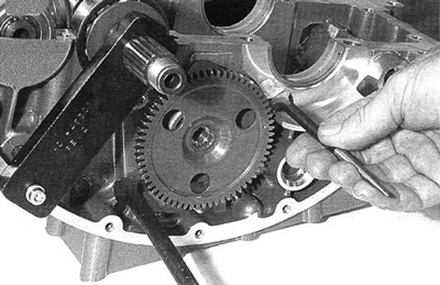
Figure 3-155. Counterbalancer gear removal
Note. Use Snap-on pliers SRPC3890 for removal/installation of the retaining rings.
Warning! Always wear proper eye protection when installing retaining rings. Use the correct retaining ring pliers. Verify that the tips of the pliers are not damaged or excessively worn. Slippage may propel the ring with enough force to cause eye injury.
4. See Figure 3-156. Remove outer retaining ring.

Figure 3-156. Retaining ring removal
5. See Figure 3-157. Thread end of BALANCER BEARING REMOVER/INSTALLER TOOLS (HD-45490) into balancer shaft.

Figure 3-157. Counterbalancer tool
6. See Figure 3-158. The counterweight must be held in the position shown to prevent binding against the case. The tool will pull the outboard bearing and balancer through the case. When the bearing is free, remove tool and bearing.
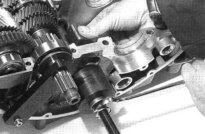
Figure 3-158. Counterbalancer outboard bearing removal
7. See Figure 3-159. Counterbalancer can be removed from engine.

Figure 3-159. Counterbalancer removal
Warning! Always wear proper eye protection when installing retaining rings. Use the correct retaining ring pliers. Verify that the tips of the pliers are not damaged or excessively worn. Slippage may propel the ring with enough force to cause eye injury.
8. See Figure 3-160. Remove outboard inner retaining ring.

Figure 3-160. Outboard inner retaining ring
9. See Figure 3-161. Remove inboard retaining ring.
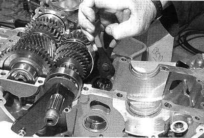
Figure 3-161. Counterbalancer inboard retaining ring
10. See Figure 3-162. Position the bearing removal insert as shown. Note the position of the flat.
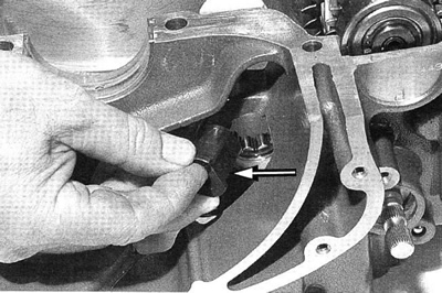
Figure 3-162. Bearing removal insert
11. See Figure 3-163. Thread puller rod into insert.
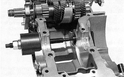
Figure 3-163. Position puller
12. See Figure 3-164. Hold screw end of puller and turn large nut to remove the bearing.
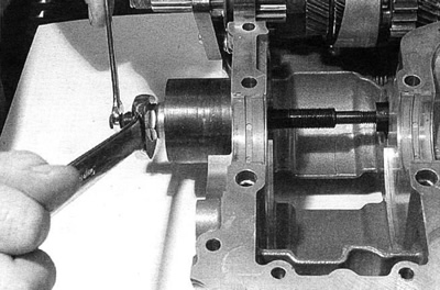
Figure 3-164. Remove bearing
Note. If counterbalancer bearings are being replaced, ALWAYS replace the inner race.
13. See Figure 3-165. Use BIG-TWIN MAINSHAFT PRIMARY BEARING RACE REMOVER AND INSTALLER (HD-34902) and WEDGE ATTACHMENT (HD-95637) to remove inboard and outboard bearing inner races.

Figure 3-165. Remove bearing race
Installation
1. See Figure 3-166. Press new inner race of inboard bearing even with the end of the counterbalancer.

Figure 3-166. Inboard bearing race
2. See Figure 3-167. Press new outboard bearing race flush against the shoulder of the balancer.
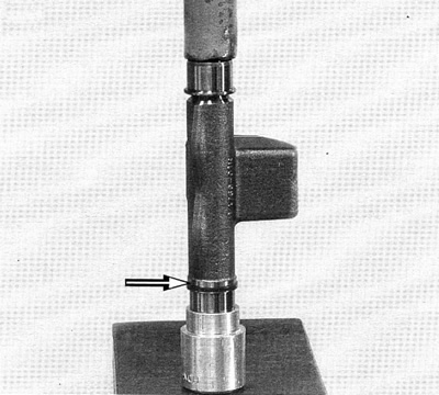
Figure 3-167. Outboard bearing race
3. See Figure 3-168. Inboard bearing race is even with the end of the counterbalancer shaft. Outboard bearing race is fully seated against shoulder of counterbalancer.
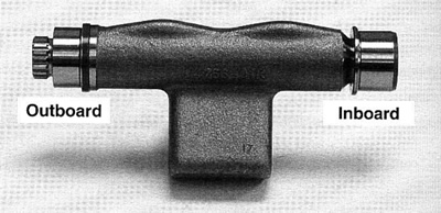
Figure 3-168. Installed inner races
Note. Use Harley-Davidson Motorcycle Oil 20W50 to thoroughly lubricate bearing surfaces and case bores before bearing installation.
Note. When installing bearings, always drive/push against the side of the bearing with the manufactures lettering/part number.
4. See Figure 3-169. Using the bearing installer from the BALANCER BEARING REMOVER/INSTALLER TOOLS (HD-45490) drive the inner counterbalancer bearing into the case with a soft faced hammer, until the retaining ring groove is visible.
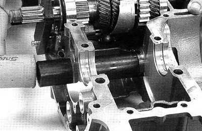
Figure 3-169. Inner balancer bearing installation
5. See Figure 3-170. Install inner retaining ring. Be certain retaining ring is fully seated.

Figure 3-170. Inner balancer bearing installation
6. See Figure 3-171. Install outboard bearing inner retaining ring. Be certain retaining ring is fully seated.

Figure 3-171. Outboard bearing inner retaining ring installation
Note. Use Harley-Davidson Motorcycle Oil 20W50 to thoroughly lubricate bearing surfaces and case bores before bearing installation process. Use Lubriplate No. 105 Assembly Grease (NAPA Part No. 765-2651) on inner races.
7. See Figure 3-172. Position counterbalancer in case.
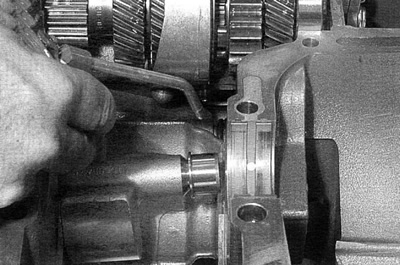
Figure 3-172. Position counterbalancer
Note. When installing bearings, always drive/push against the side of the bearing with the manufactures lettering/part number.
8. See Figure 3-173. Start bearing by hand. Insert tapered guide from the BALANCER BEARING REMOVER/ INSTALLER TOOLS (HD-45490).

Figure 3-173. Insert tapered guide
9. See Figure 3-174. Use the driver from the BALANCER BEARING REMOVER/INSTALLER TOOLS (HD-45490). Drive the bearing in with a soft faced hammer until the retaining ring groove is exposed.
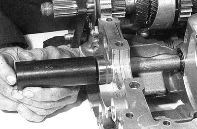
Figure 3-174. Outboard bearing installation
10. See Figure 3-175. Install out board retaining ring. Be certain retaining ring is fully seated.
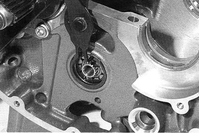
Figure 3-175. Outboard retaining ring installation
11. See Figure 3-176. Note the position of the counterbalancer master tooth flat. Align the master tooth flat with the corresponding master tooth on the balancer shaft.

Figure 3-176. Counterbalancer gear master tooth flat
12. See Figure 3-177. Install the COUNTERBALANCER ALIGNMENT PIN (HD-45311). Use a new counterbalancer gear fastener and tighten to 50 Nm (37 ft-lbs) plus 90°.
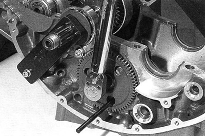
Figure 3-177. Counterbalancer gear installation
