| PART NO. | SPECIALTY TOOL |
| HD-45339 | Shift mechanism/detent retractor |
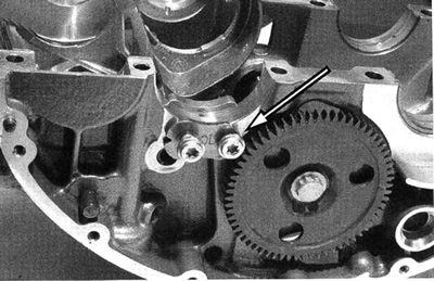
1. See Figure 3-124. Remove input shaft bearing retainer to fully expose shifting fork shaft.

Figure 3-124. Input shaft bearing retainer
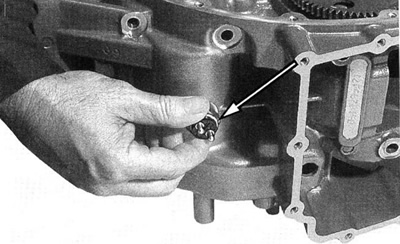
2. See Figure 3-125. Remove neutral switch.

Figure 3-125. Neutral switch
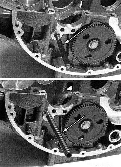
3. See Figure 3-126. Using a drift pin, pull shifter fork shaft to edge of case to free shifter forks.

Figure 3-126. Shifter fork shaft
Caution! Shafts in the Revolution transmission are closely toler-anced. Insertion of shafts must be done by hand. NEVER use a hammer or other tool to remove or install shafts. Transmission damage will result if force is used to insert shafts.
4. See Figure 3-127. Use the shifter fork shaft to position the SHIFT MECHANISM/DENTENT RETRACTOR (HD-45339).

Figure 3-127. Shift mechanism/detent retractor (HD-45339)
- a. See Figure 3-128. Engage the shifter gliding part, tighten brass thumb screw to keep gliding part in retracted position.
- b. Push shifter detent arm spring away from shifting drum star wheel. Lock in place with black knurled thumb screw.
- c. Extract shift drum shaft and remove shift drum.

Figure 3-128. Shift mechanism/detent retractor (HD-45339)
Caution! Always compress shifter pawl gliding part before shift drum detent arm moved out of position. Failure to do so could bend or break shift detent arm assembly tab.
Note. If the SHIFT MECHANISM/DENTENT RETHACTOR (HD-45339) is positioned correctly the shift drum will rotate freely.
