
1. Steering head bearings can become dented, rough or loose during normal use of the machine. In extreme cases, worn or loose steering head bearings can cause steering wobble - a condition that is potentially dangerous.
Check
2. Support the motorcycle on its centrestand if fitted, or on an auxiliary stand, so that the front wheel Is off the ground.
3. Point the front wheel straight-ahead and slowly move the handlebars from side-to-side. Any dents or roughness in the bearing races will be felt and the bars will not move smoothly and freely. Again point the wheel straight ahead, then tap the front of the wheel to one side. The wheel should 'fall' under its own weight to the limit of its lock, indicating that the bearings are not too tight. Check for similar movement to the other side. If the steering doesn't move freely through its entire lock, and it's not due to the resistance of cables or hoses, then the bearings should be adjusted as described below.
4. Next, grasp the bottom of the forks and gently pull and push them forward and backward (see illustration). Any looseness or freeplay in the steering head bearings will be felt as front-to-rear movement of the forks. If play is felt, adjust the bearings as described below.
Make sure you are not mistaking any movement between the bike and stand, or between the stand and the ground, for freeplay in the bearings. Do not pull and push the forks too hard - a gentle movement is all that is needed. Freeplay in the forks themselves due to worn bushes can also be misinterpreted as steering head bearing play - do not confuse the two.
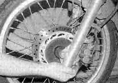
23.4. Checking for play in the steering head bearings
Adjustment
5. As a precaution, remove the fuel tank (see Chapter 4). Though not actually necessary, this will prevent the possibility of damage should a tool slip.
6. Displace the handlebars from the top yoke (see Chapter 6). Support them so the brake master cylinder is upright to prevent the possibility of fluid leakage. There is no need to remove assemblies from the handlebars, or to disconnect any cables, hoses or wiring. Note that if you do not have a socket or torque wrench, and are using a spanner to slacken and tighten the steering stem nut, the handlebars can remain in place.
7. Slacken the fork clamp bolts in the top yoke (see illustration).
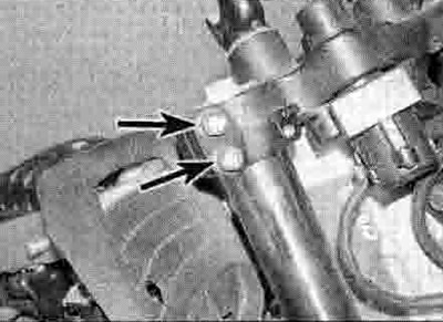
23.7. Slacken the fork clamp bolts (arrowed) on each side
8. Slacken the steering stem nut (see illustration). If you have the Honda special tool for the adjuster nut, or a suitable equivalent (which can be made by cutting castellations into an old socket, or a peg spanner to which a torque wrench can be applied), or are using a C-spanner, release any cables and wiring from guides on the top yoke, and where if necessary (according to model) displace the fusebox, then unscrew and remove the steering stem nut and washer, then gently ease the top yoke up off the fork tubes and position it clear of the head bearings, using a rag to protect other components (see illustration). Otherwise leave the yoke in position.
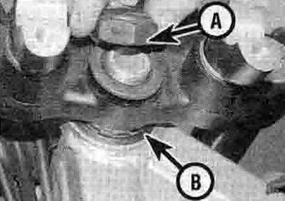
23.8a. Slacken or unscrew the steering stem nut (A). The adjuster nut (B) is under the yoke

23.8b. If required, gently ease the yoke up off the forks
9. If you don't have the special tool or equivalent, use a drift located in one of the notches to slacken the adjuster nut slightly until pressure is just released, then tighten it until all freeplay is removed, yet the steering is able to move freely (see illustration 23.8a). The object is to set the adjuster nut so that the bearings are under a very light loading, just enough to remove any freeplay, but not so much that the steering does not move freely from side to side as described in the check procedure above.
10. If the Honda tool or a suitable socket or peg spanner is being used, slacken the adjuster nut slightly until pressure is just released, then tighten it to the torque setting specified at the beginning of the Chapter, and this should give the correct loading. Turn the steering from lock-to-lock five times after tightening and recheck the adjustment or torque setting. Do not rely on the torque setting alone and assume the loading to be correct - check the physical feel as described as well. If the bearings cannot be correctly adjusted, disassemble the steering head and check the bearings and races (see Chapter 6). If a C-spanner is being used, adjust according to the procedure in Step 9 (see illustration).
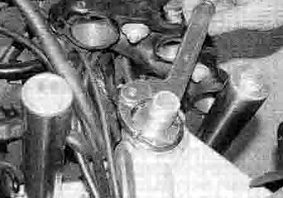
23.10. Adjust the bearings as described using either a C-spanner or a drift, or one ol the special tools described
Caution: Take great care not to apply excessive pressure because this will cause premature failure of the bearings.
11. If displaced, fit the top yoke onto the steering stem, then install the washer and nut (see illustration 23.8b and a).
12. Tighten the steering stem nut to the torque setting specified at the beginning of the Chapter. Now tighten both the fork clamp bolts to the specified torque (see illustration 23.7).
13. Check the bearing adjustment as described above and re-adjust if necessary.
14. Install the handlebars if displaced (see Chapter 6), and the fuel tank (see Chapter 4).