
Inspection
Remove the left rear crankcase cover (page 2-2).
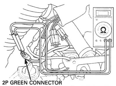
Disconnect the side stand switch 2P green connector. Check for continuity at the switch side of the 2P green connector.
There should be continuity with the side stand retracted.
There should be no continuity with the side stand down.
Removal
Remove the left rear crankcase cover (page 2-2).
Disconnect the side stand switch 2P green connector.

Support the motorcycle securely.
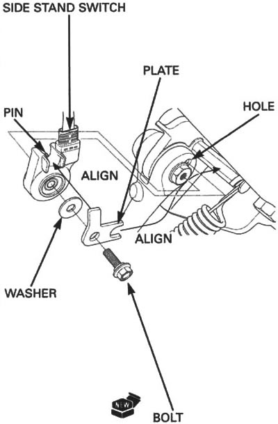
Remove the bolt, plate, washer and side stand switch from the side stand pivot.
Installation
Install the side stand switch aligning the switch pin with the side stand hole.
Install the washer and plate aligning the tab on the plate with the switch groove and the groove on the plate with the return spring holding pin.
Install and tighten the new side stand switch bolt to the specified torque.
Torque: 10 N·m (1.0 kgf·m, 7 lbf·ft).
Install the removed parts in the reverse order of removal.