
Details
The electronic combination meter unit, superior to the conventional type in weight and durability is installed on the ZX600-J. The hall IC-type speed sensor is installed on the ZX600-J together with it, which needs no cable and speedometer gears. Its construction and operation are described as follows;
Construction & operation
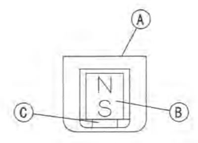
The speed sensor [A] consists of a magnet [B] and the Hall IC [С].
The Hall IC consists of Hall element [A], the differential amplifier [B], the high pass filter [C], the comparator [D] and the output transistor [E].
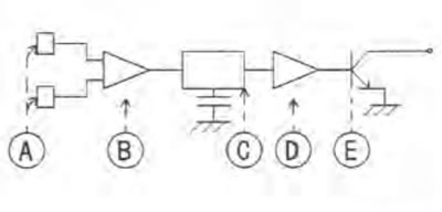
Hall element
The semi-conductors (e.g. CaAs, InAs, InSb) are called as mentioned above. The magnetic induction applied on the two (2) Hall elements will be converted into the voltage, and outputted.
Differential amplifier
This can output the difference between output powers of the two (2) Hall elements.
High pass filter
Sensitivity of the two (2) Hall elements.
Surface magnetic Induction of a magnet.
Relative positions of the Hall element, magnet, and detector gear.
Able to cancel the DC off-set because of scattering of differential output.
Comparator & output transistor
Able to output the square wave in accordance with the magnetic induction alternation with the transistor turning on or off.
The magnetic induction passing through the Hall element will be changed In accordance with the relative position of the sensor and the rotor nut [A] installed on the engine sprocket will be rotated.
Amount of magnetic induction:
- when large [B]
- when small [C]
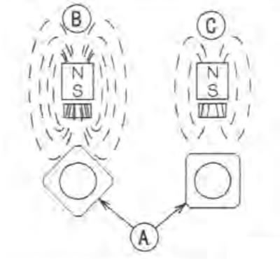
In the internal system of the Hall IC, the switch is operated in accordance with the magnetic induction alternator. This makes the square wave equal to the pulse of the rotor nut output.
- Amount of magnetic induction when large [A]
- Amount of magnetic induction when small [B]
- Operating point [C]
- Returning point [D]
- When high voltage [E]
- When low voltage [F]
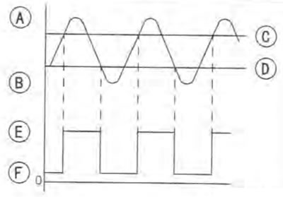
The vehicle speed is indicated in the speedometer, altering the pulse of this square wave.
Speed sensor inspection
Refer to the Electrical System.