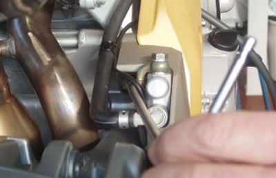
Function
To indicate the vehicle speed by reading the secondary transmission shaft rotation.
Operating principle
Hall-effect sensor: a square-wave pulse is generated with voltage between 0 and approximately 0.3-0.4V.
Level in wiring diagram: Speed sensor
Location:
- on the vehicle: right side, near the clutch cover.
- connector: on the sensor.
Pin-out:

1. Ground connection; 2. Output signal; 3. Supply voltage 5V
Caution! Before carrying out any troubleshooting, carefully read the general troubleshooting concepts for electrical devices at the beginning of the check and control section in the electrical system chapter.
Axone: parameters
Vehicle speed: km/h
Axone: logic errors
Sensor/vehicle speed signal P0500 - over maximum limit/ signal not valid.
Error cause
If over the maximum limit: excessive signal frequency has been detected at PIN 49 VEHICLE. If signal is not valid: a fault in the signal (no signal, short circuit to positive, open or earthed circuit, defective sensor, open circuit, defective measuring cam, etc.) has been detected at VEHICLE PIN 49. This requires a longer recognition time that is counted from zero each time the clutch is operated, the gear is set to neutral or the engine is shut off.
Troubleshooting
if over the maximum limit: replace the sensor.
Signal not valid: check the speed sensor connector and the Marelli control unit connector: if not OK, restore. If OK, check that, with key set to ON and the sensor connector disconnected, there is continuity on PIN 1 with the ground connection. If there is no continuity, set the key to OFF and check that there is continuity between ENGINE PIN 36 and PIN 1 of the sensor connector. If there is not, replace the control unit; if there is, check that there is voltage at PIN 3 coming from the control unit (approximately 5V): if there is no voltage, set the key to OFF and check that there is continuity between the ENGINE PIN 13 and PIN 3. If there is continuity, replace the control unit; if there is not, restore the cable harness; if there is 5V voltage, set the key to OFF and check that there is continuity between the VEHICLE PIN 49 and the sensor PIN 2: if there is no continuity, restore the cable harness. If there is continuity, check that the cam that reads the signal is in good conditions: if it is not, replace it. If it is OK, replace the sensor.
Sensor removal
Remove the rear shock absorber.
Undo and remove the screw.

Disconnect the speed sensor connector.

Rotate the speed sensor and slide it off upwards.
Note.
It is strictly forbidden to use the vehicle with the speed sensor disconnected.
Besides vehicle speed, this sensor communicates other operation parameters to the control unit.
