Pay attention to the following points:
Note:
- The engine mounting nuts are self-locking.
- Once the nut has been removed, it is no longer of any use. Be sure to use new nuts, and then tighten them to the specified torque.

| ITEM | N·m | kgf·m | lb·ft |
| A F | 45 | 4.5 | 32.5 |
| B G | 12 | 1.2 | 8.5 |
| C | 93 | 9.3 | 67.5 |
| D | 25 | 2.5 | 18.0 |
| E H | 55 | 5.5 | 40.0 |
| I | 35 | 3.5 | 25.5 |
Before installing the engine assembly, install the spacer (A), collar (B) and engine thrust adjuster (C).

Install the collar (1) onto the crankcase properly as shown.

Install the left engine mounting bracket (2).
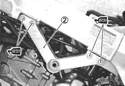
Apply THREAD LOCK to the engine mounting bracket bolts.
Tighten the engine mounting bracket bolts to the specified torque.
- Engine mounting bracket bolt: 35 N·m (3.5 kgf·m, 25.5 lb·ft)
- 9900°-32050: THREAD LOCK "1342"
Put the drive chain on the driveshaft.
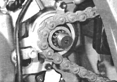
Gradually raise the engine assembly and align all the bolt holes.
Install the engine mounting bolts and tighten them temporarily.
Tighten the engine mounting thrust adjusters to the specified torque.
- Engine mounting thrust adjuster: 12 N·m (1.2 kgf·m, 8.5 lb·ft)

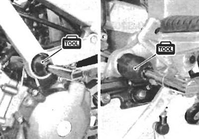
Tighten the engine mounting thrust adjuster lock-nuts to the specified torque with the special tool.
- 09940-14990: Engine mounting thrust adjuster socket wrench
- Engine mounting thrust adjuster lock-nut: 45 N·m (4.5 kgf·m, 32.5 lb·ft)
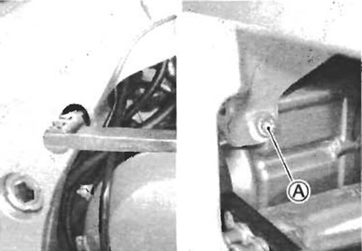
After tightening the engine mounting bolt, tighten the pinch bolt (A).
- Engine mounting bolt: 55 N·m (5.5 kgf·m, 40.0 lb·ft)
- Engine mounting pinch bolt (A): 25 N·m (2.5 kgf·m, 18.0 lb·ft)
Tighten the engine mounting nuts to the specified torque.
- Engine mounting nut (A): 93 N·m (9.3 kgf·m, 67.5 lb·ft)
- Engine mounting nut: 55 N·m (5.5 kgf·m, 40.0 lb·ft)

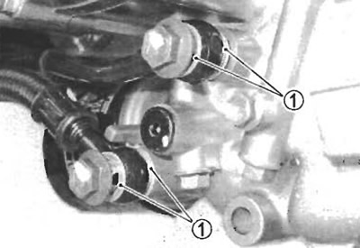
Install the washers and tighten the union bolt to the specified torque.
- Oil cooler union bolt: 23 N·m (2.3 kgf·m, 16.5 lb·ft)
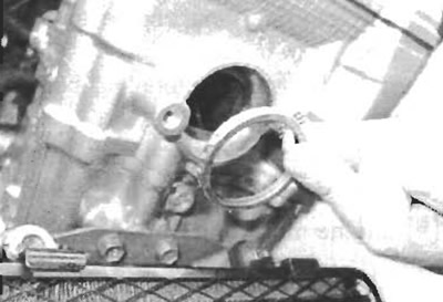
Install the new gaskets.
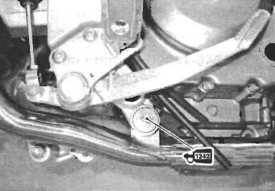
Apply THREAD LOCK to the muffler mounting bolt.
- 99000-32050: THREAD LOCK "1342"
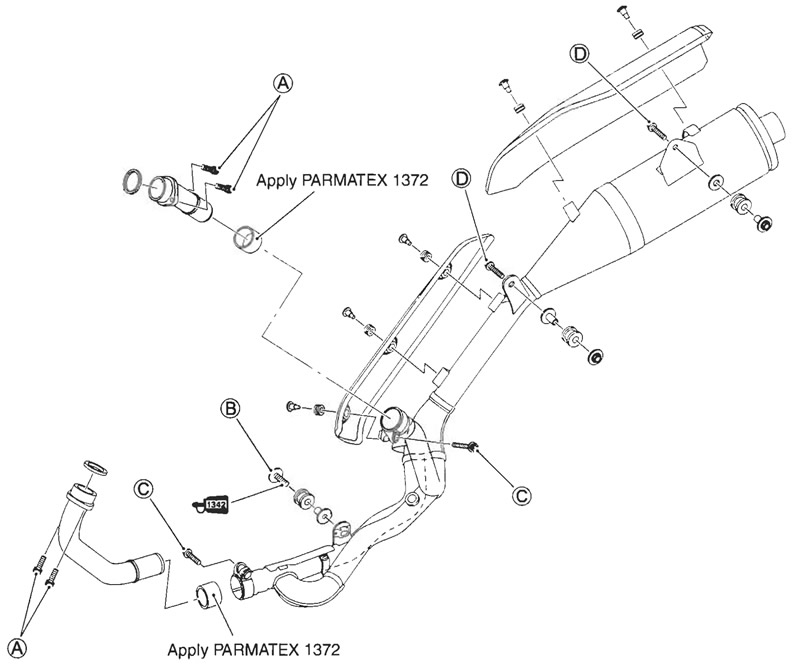
| ITEM | N·m | kgf·m | lb·ft |
| A B C D | 23 | 2.3 | 16.5 |
Adjust the brake pedal height.
- Brake pedal height (A): Standard: 20-30 mm (0.79-1.18 in)

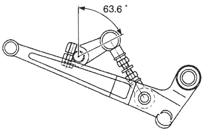
Install the gearshift arm as shown.
- Gearshift arm angle (A): Approx. 63.6°
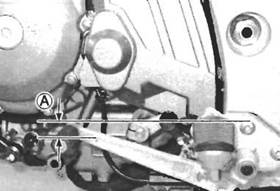
Adjust the gearshift lever as shown.
- Gearshift lever height (A): Standard: 20-30 mm (0.79-1.18 in)
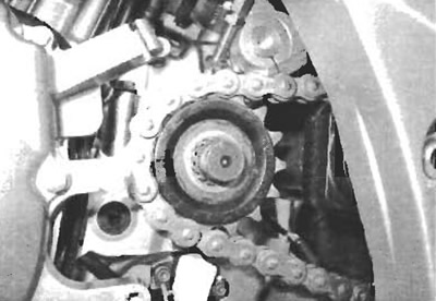
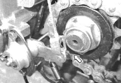
Install the engine sprocket.
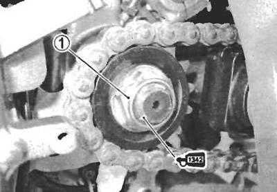
Install the engine sprocket and the washer.
Apply a small quantity of THREAD LOCK to the drive shaft thread portion.
- 99000-32050: THREAD LOCK "1342"
Tighten the engine sprocket nut (1) to the specified torque.
- Engine sprocket nut: 145 N·m (14.5 kgf·m, 105 lb·ft)
Bend the lock washer.
Adjust the drive chain slack. (2-21)
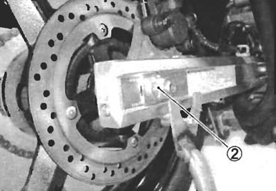
Tighten the rear axle nut (2) to the specified torque.
- Rear axle nut: 100 N·m (10.0 kgf·m, 72.5 lb·ft)
Install the cotter pin. (For E-03, 28, 33)
Apply SUZUKI SUPER GREASE to the clutch push rod and install it.
- 99000-25030: SUZUKI SUPER GREASE "A" (USA)
- 99000-25010: SUZUKI SUPER GREASE "A" (Others)
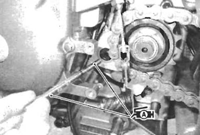
Install the clutch cable to the generator cover temporarily.
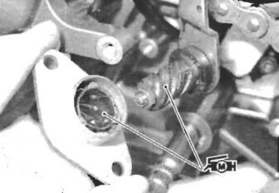
Apply SUZUKI MOLY PASTE to the clutch release.
- 99000-25140: SUZUKI MOLY PASTE
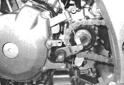
Assemble the clutch release so that the lever arm (A) will be angle of 80 degree with axle (B).
Adjust the clutch cable play. (2-17)

Note: After installing the clutch release, make sure that there is clearance between the clutch cable end and the driveshaft end.
After installing the engine, route the wire harness, cables and hoses properly. (9-16)
Adjust the following items.
