
Warning! Before starting work, ensure the motorcycle is stabilised and adequately supported. This will help prevent it from falling and causing injury to the operator or damage to the motorcycle.
1. Remove the fuel tank (see page 11.100).
2. Drain the cooling system (see page 12.6).
3. Remove the exhaust header system (see page 11.134).
4. Remove the throttle bodies (see page 11.122).
5. Remove the oil tank (see page 9.16).
6. Remove the camshafts (see page 3.9).
7. Disconnect the top and bypass hoses from the cylinder head.

1. Top hose; 2. Bypass hose
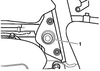
8. Disconnect the coolant temperature sensor and low oil pressure switch connections.

1. Low oil pressure warning light switch
9. Remove both engine in-fill panels.
In-fill panel
10. Identify the position of each of the tappet buckets and shims before removing them from the head.
11. Remove the sound suppression bolt from the cam chain chest.
12. Progressively release the cylinder head bolts in the order shown below.

Head bolt release sequence
13. Remove the head bolts including two smaller bolts situated at the front of the engine.
14. Remove the head from the crankcase.
Note: If necessary, lightly tap the head with a soft-faced mallet to break the gasket seal.
15. Remove and discard the head gasket.
16. Remove the cylinder liners (see page 5.18).
Note: Cylinder liners must be resealed if the head is removed.
Inspection
1. Thoroughly clean the surface of the cylinder head and check for damage and/or pitting of the combustion chambers.
2. Using a straight edge and feeler gauges, check the cylinder head gasket face for warp, which could lead to gasket failure. Replace the cylinder head if warped beyond the flatness limit.
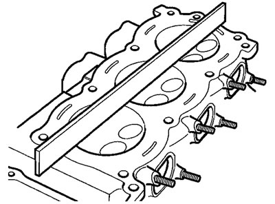
Checking head flatness
| Cylinder head flatness tolerance | 0.030 mm |
3. Check the cam chain rubbing blades. Renew if worn or damaged.
Caution! Ensure all traces of fluid (coolant, oil etc). are removed from the threaded holes in the crankcase. Should any fluid remain in any of the threaded holes, severe crankcase damage could result from hydraulic locking of head bolts on assembly of the engine.
Installation
1. Thoroughly clean the upper faces of the crankcase and liners. Also clean the liner to crankcase mating faces.
2. Fit the cylinder liners (see page 5.19).
3. Move the cam chain rubbing blades to a position that allows the head to fit over them.
4. Ensure that both head dowels remain in position in the crankcase.
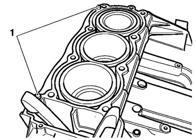
1. Dowels
5. Position a new cylinder head gasket to the crankcase.
6. Lower the cylinder head over the cam chain rubbing blades and locate it onto the dowels.
Caution!
- Cylinder head bolts must never be reused and must always be replaced if removed or loosened.
- Use the correct procedure to tighten the cylinder head bolts carefully following the three-stage procedure below. This will ensure the long-term reliability of the cylinder head gasket.
- Failure to follow the correct tightening procedure or reuse of old head bolts may lead to engine damage and premature failure of the cylinder head gasket.
7. In the order shown below, tighten the cylinder head bolts in three stages as follows:

Cylinder head bolt tightening sequence
8. In the sequence shown above, tighten bolts 1 through 8 to 20 Nm.
9. In the sequence shown above, tighten bolts 1 through 8 to 50 Nm.
10. In the sequence shown above, tighten bolts 1 through 8 through a further 90° using tool T3880105 or similar to measure the torqueangle.
11. Tighten bolts 9 and 10 to 12 Nm.
12. Lubricate the tappet buckets with a 50/50 solution of molybdenum disulphide grease and engine oil, then refit them and the valve shims to their original locations in the head.
13. Refit the camshafts (see page 3.12).
14. Check and adjust the valve clearances (see page 3.14).
15. Reconnect the coolant temperature sensor.
16. Refit the bypass and top hoses.
17. Refit the oil tank (see page 9.16).
18. Refit the throttle bodies (see page 11.123).
19. Refit the exhaust system (see page 11.136).
20. Refill the cooling system (see page 12.7).
21. Refit the fuel tank (see page 11.101).
22. Refit both engine in-fill panels, tightening the fixings to 4 Nm.
23. Start the engine and allow it to idle while checking for air, oil, coolant and exhaust leaks. Rectify as necessary.
24. Check and top up the cooling system (see page 12.5).
25. Check and top up the oil level (see page 9.7).