Caution! Once the electrical system is refitted, the connectors reconnected and clamps and retainers restored, carry out the checks indicated under "special checks for the correct connection and laying of cables" in the "electrical system installation" section.
Table A - switches
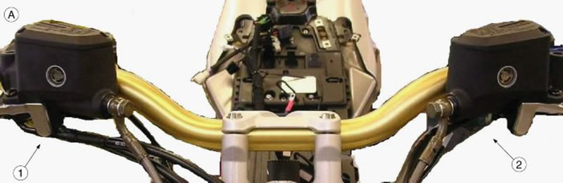
1. Right switch cable harness; 2. Left switch cable harness
Introduce carefully the cap on the cable harnesses (1 and 2) of the switches.
Table B - right switch cable harness retainer
Fasten the right switch cable harnesses with a rubber clamp.
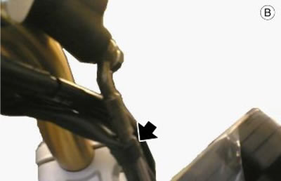
Table C - left switch cable harness retainer
Fasten the left switch cable harnesses with a rubber clamp.
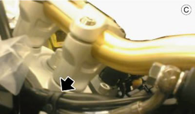
Table D - clutch cable, throttle cable
With a small clamp, not pulled clamp, fasten the clutch cable to the throttle cable.
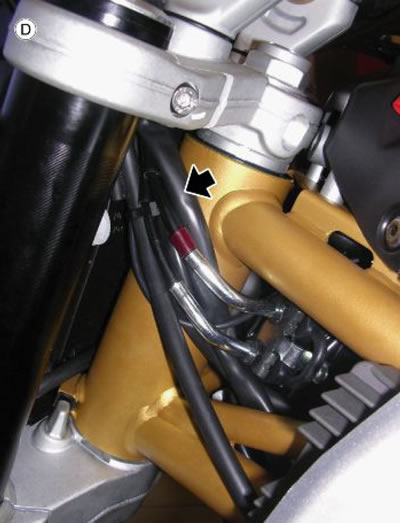
Table E - instrument panel cables
Fasten the instrument panel cable braid to the chassis with a medium clamp.
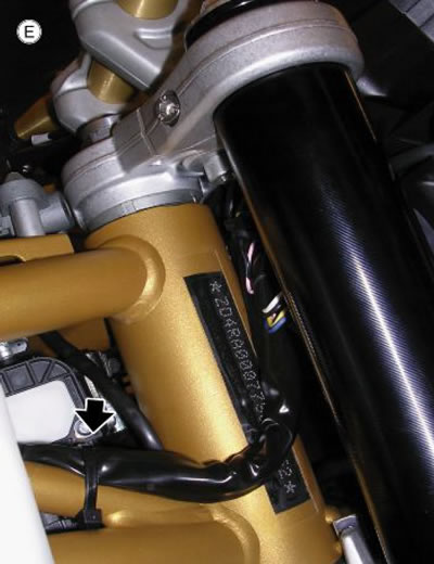
Table F - instrument panel cables
1. The two medium clamps shall be positioned so that they match the corresponding sections of chassis indicated through two turns of red belt.
2. Place the clamp as close as possible to the chassis vertical tube.
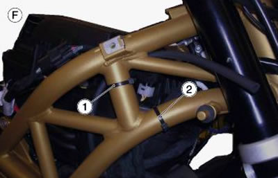
Table G - air temperature connector and headlamp cable
Use a small clamp to fasten the air temperature connector and the headlamp cable to the main cable harness.
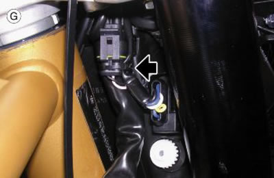
Table H - coil cable
Fasten the coil cable with a small clamp.
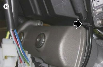
Table I - housing and central cable grommet
1. The housing containing light switch and key connectors shall be placed freely over the branch with the clamp and not fixed.
2. Place medium clamps on the central cable grommet that holds only the branch that leads to the filter box left side.
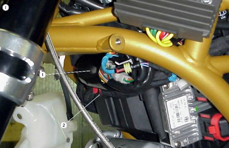
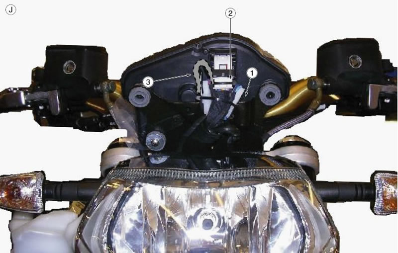
Table J - instrument panel
1. Place a small clamp on the left turn indicator connector and the main trunk.
2. The Immobilizer aerial connector is fitted between the plate and the instrument panel.
3. Lift the external air temperature sensor upwards once it is connected.