
Caution! Once the electrical system is refitted, the connectors reconnected and clamps and retainers restored, carry out the checks indicated under "Special checks for the correct connection and laying of cables" in the "Electrical system installation" section.
Table A - Control unit, main cable harness, horn and neutral sensor cables

1. ECU; 2. Engine Connector; 3. Vehicle Connector; 4. ECU ground connection; 5. Horn and neutral sensor cables; 6. Main cable harness
The horn and neutral sensor cables shall be laid over the water pipe upon installation.
Table B - under seat cable harness
1. Use small clamps to fasten the cables.
2. Use medium clamps to fasten the main cable harness.

Table C - main cable harness
The main cable harness is laid between the relay and the fall sensor, under the fall sensor connector.
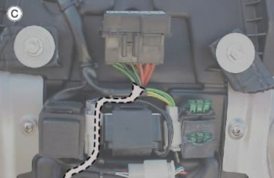
Table D - diagnosis connectors
Fasten both diagnosis connectors with a small clamp, under the cable harness main branch.
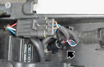
Table E - cable harnesses under the tank
1. Fasten the pipe with two medium clamps.
2. The flywheel and side stand cables shall be laid through the cable guide screwed to the filter housing.
3. Bunch the cables with clamps.
4. Fasten with a clamp cables on the filter housing and the rear cylinder coil.

Table F - cable harnesses under the tank
1. Place clamps at the connector sides.
2. Mark the connection on the left side using the BLUE belt.
3. Mark the connection on the right side using the WHITE belt.
4. Fasten with a medium clamp.

Table G - handgrip sensor connector
1. Fitting the connector in the handgrip sensor.
2. Closing the connector block.
3. During step (1), move the hook (3) forwards.
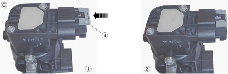
Table H - left side cable harness under the tank
Identify the regulator output with the WHITE belt.
1. Fasten the cable harness with a clamp.
2. Connector for resistance module.
3. Fasten the cables with a clamp and hold also the control unit upper branch.

Table I - pick-up and engine control unit cable harnesses
1. Cable harness path towards the engine control unit connectors.
2. Pick-up cable harness path.
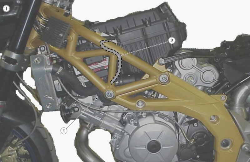
Table J - right side
1. Use a small clamp to keep the cable fixed to the oil bulb cap.
2. Use a small clamp behind the pipe so that the oil and start-up cable is tightened to the rear pipe.
3. Fasten the cable with medium clamps.

Table K - neutral sensor cable harness
Place the idle sensor cable harness as shown and fasten it with a small clamp (1) where indicated.
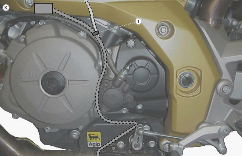
Table L - lambda probe
Place two clamps to fasten the cable harness to the chassis, as indicated:
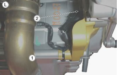
1. medium clamp; 2. small clamp.
Table M1 - filter box cable harness
Place both throttle valve position sensors.
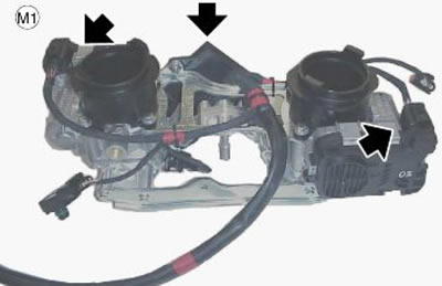
Table M2 - sensors
Place the two sensors.
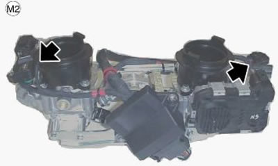
Table M3 - clamps
Fasten cable harnesses with clamps.
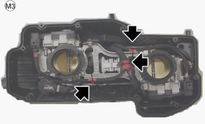
Table M4 - filter box
Insert the throttle body, with the cable harness correctly fixed, in the filter box.
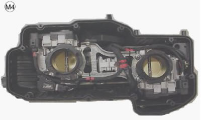
Table N - ground lead and start-up cable
Fit the ground lead following the path drawn in figure that will not be visible on the vehicle once fully assembled.
As indicated above, the ground lead is laid behind the filter casing pipe.
As regards the lower section, the cable is laid behind the starter motor plate.
In the central position, insert a small clamp joining the ground lead and the oil cable to the smallest pipe.

Table O - ground lead and start-up cable
1. Direct the cable as shown in figure.
2. Before fitting the cable, push the sheath to the panel terminal so as to hide the RED cable (see box).
3. Fasten the cable with a clamp 10-mm (0.39 in) long.
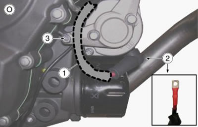
Table P - ground lead and start-up cable
1. Fasten the cable with clamps where indicated.
2. Be careful not to hold the MAP sensor pipe with the clamp.
3. Place the cable harness as shown.
