
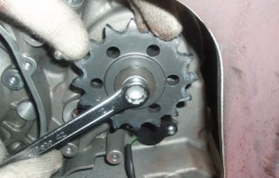
Use the special tool to undo and remove the crankshaft fastener nut, retrieving the washer.
Specific tooling: 020711Y Engine pinion locking

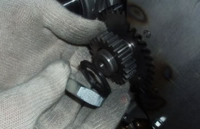
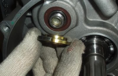
Use a commercially available extractor to remove the crankshaft gear.

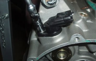
Remove the gearbox control rod, retrieving the washer.
Undo and remove the screw fixing the speed sensor.
Remove the speed sensor with caution.
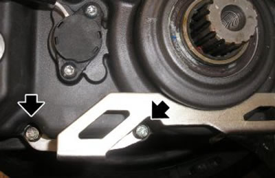
Heat the screws of the gearbox selector mounting plate.

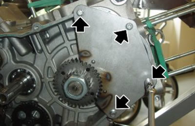
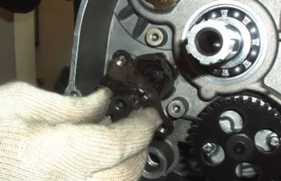
Undo and remove the three screws fastening the gearbox selector mounting plate.
Remove the plate complete with selector
Undo the two neutral sensor fastener screws.

Remove the neutral sensor.
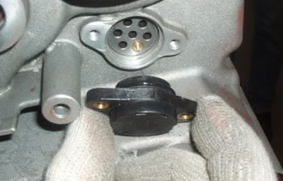
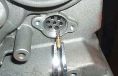
Retrieve the sensor contact complete with spring.
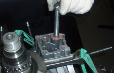
If the pinion has been removed, refit, fastening with the special tool.
Specific tooling: 9100896 Clutch bell locking tool

The tone wheel is fixed with Loctite threadlock and must therefore be heated with a special hot air gun, taking particular care not to heat excessively.
Remove the speed sensor tooth with the special tool.

When refitting, fix the tone wheel with strong Loctite threadlock.
Specific tooling: 020715Y Tone wheel removal
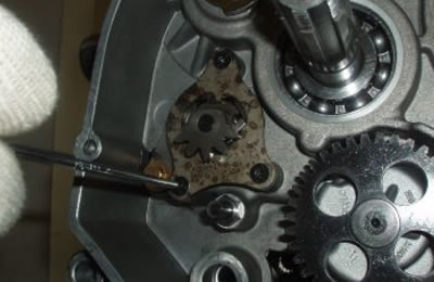
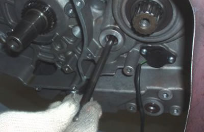
Undo and remove the selector drum fastener screw.

Remove the selector drum.

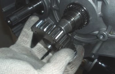
Remove the pinion.
Remove the clutch control rod.
Working on the left hand side, undo and remove the nine M8 crankcase fastener screws.
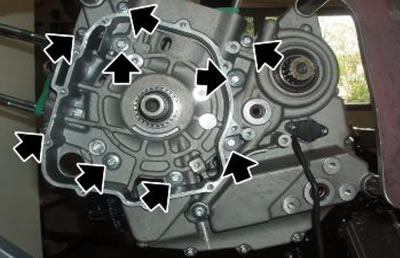
Working on the left hand side, undo and remove the nine M6 crankcase fastener screws.

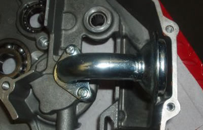
Remove the fuel vapour breather pipe mounting plate.
Caution! During reassembly, remember to fit the fuel vapour breather pipe mounting plate near the pinion.
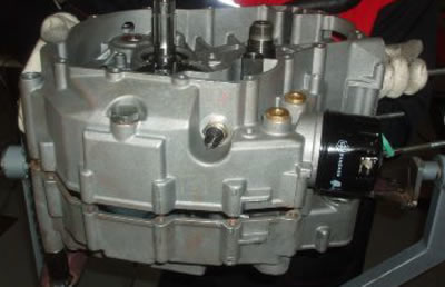
Rotate the engine and the engine mounting into a horizontal position.
Undo and remove the pin, then retighten by one turn to give the crankcase halves free play and verify tightness.
Caution! Take particular care to ensure that the engine and engine mounting are stable and ensure that the engine is securely fastened to the mounting plate.

Remove the two screws fastening the mounting.

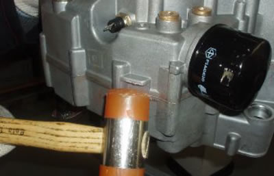
Separate the crankcase halves by giving short taps with a rubber mallet.
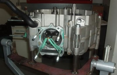
Open the crankcase halves.

Retighten the two screws to the engine mounting.
If necessary, undo and remove the two screws fastening the rose pipe.
Remove the rose pipe.
See also specifications for this operation.