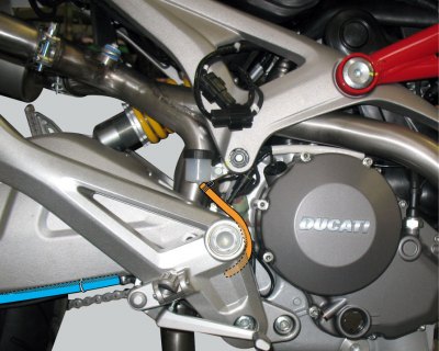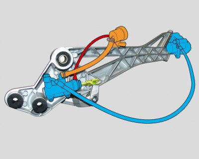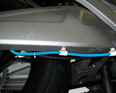
1. Banjo bolt; 2. Sealing washer; 3. Rear brake hose; 4. Hose clip; 5. Pin; 6. Spring; 7. Adjuster screw; 8. Rubber; 9. Brake pedal lever; 10. Nut; 11. Quick-release fastener; 12. Washer; 13. Switch; 14. Bush; 15. Fork; 16. Hose; 17. Rear brake master cylinder; 18. Screw; 19. Pushrod; 20. Rubber boot; 21. Screw; 22. Plug; 23. Fluid reservoir assembly; 24. O-ring; 25. Nut
Caution! Bold reference numbers in this section identify parts not shown in the figures alongside the text, but which can be found in the exploded view diagram.
Removal of the rear brake master cylinder
Warning! The brake master cylinder manufacturer advises against servicing the brake master cylinder due to the safety critical nature of this component. Incorrect overhaul of this component could endanger rider safety.
Maintenance operations on these units are limited to replacing the following parts: control lever, reservoir unit, reservoir fasteners and master cylinder fasteners.
| Operation | Section reference |
| Drain the braking system | Draining the brake circuit |
Undo the screw (21) and remove the reservoir (23) complete with the hose (16).
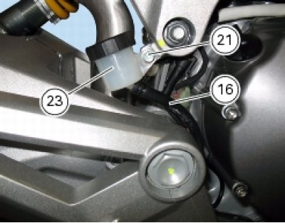
Remove the footrest bracket (Removal of the footrest brackets).
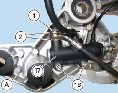
Unscrew the screws (18) securing the rear brake master cylinder (17) to the footrest bracket (A).
Unscrew the banjo bolt (1) from the master cylinder (17), recovering the two sealing washers (2).
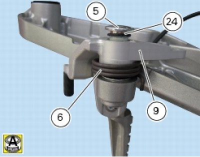
Unscrew the pin (5) securing the rear brake pedal lever to the footrest bracket and remove the spring (6), the complete pedal lever (9) and the O-ring (24).

Disassembly of the rear brake control
The brake master cylinder is supplied only as a complete unit; internal components cannot be replaced.
To disassemble master cylinder external components, follow the indications given in the exploded view at the beginning of this section.
If the brake pedal (9) inner bushing (14) needs to be renewed, fit the new bushing using a suitable press and position it so that it is set in 2 mm from the outer face of the pedal.

To disassemble the various parts of the system, refer to the exploded view at the beginning of this chapter.
Warning! After working on the rear brake control, check the operation of the brake pedal following the instructions given in Adjusting the position of the gearchange and rear brake pedals.
Refitting the rear brake master cylinder
Lubricate the O-ring (24) eand install it on the pin (5).
Lubricate also the other O-ring (24).
Fit the spring (6) and the pedal pivot pin (5) to the footrest bracket, pushing the pivot pin fully home and positioning the spring (6) as shown in the figure.
Apply threadlocker to the threads of the pivot pin (5).

Refitting is the reverse of removal; in particular, tighten the screws (18) to the specified torque (Frame torque settings).

Note: If the case of renewal of the master cylinder-caliper pipe (3) and the master cylinder-reservoir pipe (16), take care to ensure that the pipe unions are correctly oriented on the master cylinder.
Locate the hoses (3) and (16) as shown in the figure, then tighten down the banjo bolt (1) to the specified torque (Frame torque settings).

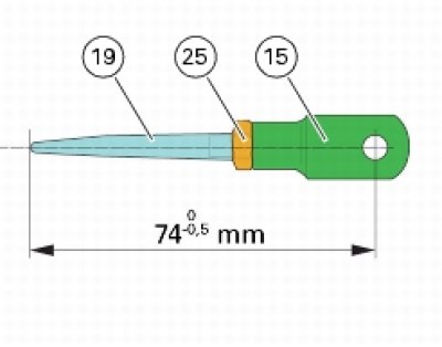
If the pushrod (19), clip (11) and clevis (15) assembly has been dismantled, reassemble by screwing the nut (25) onto the pushrod (19) and then screw the pushrod into the clevis (15) to obtain the measurement indicated in the figure.
Restrain the pushrod and tighten the nut (25) against clevis (15) to the specified torque (Frame torque settings).
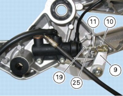
Fit the rear brake control rod on the pivot bolt (9), securing it with the clip (11).
Now lubricate the other end of the pushrod (19) with the recommended grease and insert it in the master cylinder (1).
Refit the footrest bracket to the frame (Refitting the footrest brackets).
| Operation | Section reference |
| Fill the brake system | Filling the brake system with fluid |
Positioning of rear brake hose
