
Removing and installing brake light switch
- Remove right engine spoiler.
See Group 46.
- Remove the right footrest plate
- Open the cable ties.
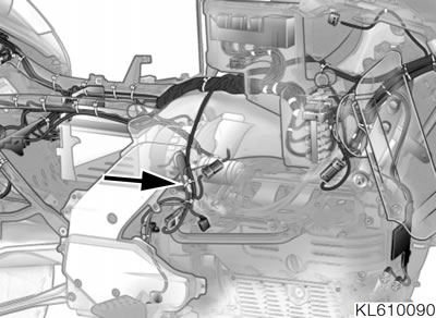
- Disconnect plug (arrow).
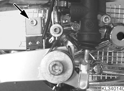
- Release the fastener (arrow).
- Remove retaining plate and brake light switch with cable.
- Installation is the reverse of the removal procedure: pay particular attention to the following.
- Route cables correctly and secure with cable ties.
- Check foot brake light switch; adjust if necessary
Tightening torques:
- Brake light switch to footrest plate — 5 Nm (clean thread + Loctite 243)
- Footrest plate to frame — 21 Nm
Adjusting brake light switch
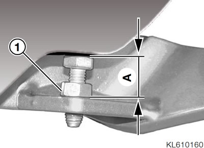
- Slacken locknut (1).
- Set stop of foot-brake lever to distance "A".
- Tighten the locknut.
- Check operation of brake-light switch.
Warning: Check piston rod play.
Setting:
- Distance "A" — 14 mm (0.55 in)
Tightening torque:
- Stop, footbrake lever — 7 Nm