Removal
Note. The removal and installation steps listed apply when replacing the entire switch assembly, a switch housing or the handlebar.
Warning! To prevent accidental vehicle start-up, which could cause death or serious injury, remove main fuse before proceeding.
1. Remove main fuse.
2. Using a T25 TORX drive head, loosen but do not remove the upper and lower switch housing screws.
3. Using a T27 TORX drive head, remove the two screws with flat washers securing the handlebar clamp to the clutch lever bracket. Remove the clutch hand lever assembly and clamp from the handlebar.
4. Remove the upper and lower switch housing screws.
5. Remove the left hand grip from the end of the handlebar if damaged. See 2.30 HANDLEBAR, Left Hand Grip.
Disassembly
1. Remove the upper and lower switch housing screws.
2. If replacing lower housing switches, perform next step before continuing to repair section. If replacing upper housing switches, proceed directly to repair section.
3. Loosen the upper screw securing the handlebar clamp to the clutch lever bracket. Remove the lower clamp screw with flat washer.
Switch repair and replacement
Switch and lead replacement
After cutting off the connector terminals, pull the leads of faulty switches through the conduit. Route replacement switch leads through the conduit. Terminate the leads at the connector. If necessary, replace only the switches.
Switch only replacement: upper housing
Note. If only one switch is faulty, replace the horn switch and high/low beam switch as a single assembly.
1. See Figure 6-148. From inside the switch housing, remove the screw with lockwasher (4) to release the bracket (5). Remove bracket and switch assembly from the housing.

Figure 6-148. Upper housing without splices: 1. Horn switch; 2. High/low beam switch; 3. Conduit; 4. Screw with lockwasher; 5. Bracket
2. Move cable conduit (3) from beneath wing of bracket. Cut wires 0.25 in (6.4 mm) from old switches (1, 2). Discard old switch and bracket assembly.
3. Slide conduit forward over cut ends of switch wires and cut off 0.5 in (12.7 mm) of conduit (3) material. Push conduit back to access switch wires.
4. Separate the new horn switch (1) and high/low beam switch (2) wires into two bundles.
5. See 6.33 HANDLEBAR SWITCH ASSEMBLIES for information on splicing and general repair practices.
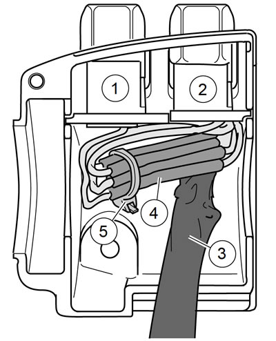
6. See Figure 6-149. Loop switch wires.

Figure 6-149. Upper housing with splices: 1. Horn switch; 2. High/low beam switch; 3. Conduit; 4. Splices; 5. Cable strap
7. See Figure 6-148. Route wires downstream of splices beneath wing on high/low beam switch side of bracket.
8. See Figure 6-149. Install a new 7.0 in (177.8 mm) cable strap (5) beneath wing on horn switch side (1) of bracket and capture wire splices (4).
9. Place switch assembly into upper housing aligning hole in bracket with threaded hole in boss. Be sure that bracket is fully seated. The step at the edge of the boss captures the bottom edge of the bracket. Tabs on each side of the bracket fit in slots cast into the housing.
10. See Figure 6-148. Install screw and lockwasher (4) to secure bracket (5) inside housing. Verify that wing on high/low switch (2) side of bracket captures edge of conduit (3) as shown.
11. Securely tighten cable strap to draw splices to bracket. Trim cable straps.
Switch only replacement: lower housing
1. From inside the switch housing, carefully cut cable strap to free conduit from the turn signal switch bracket.
2. Remove screw with lockwasher to release the turn signal switch bracket. Remove the bracket and switch assembly from the housing.
Turn-left signal switch only
1. Cut wires 1.5 in (38.1 mm) from old turn signal switch. Discard switch assembly.
2. See 6.33 HANDLEBAR SWITCH ASSEMBLIES for information on splicing and general repair practices.
Clutch interlock switch only
1. See Figure 6-150. Cut wires 0.25 in (6.4 mm) from old switch. Discard switch assembly.

Figure 6-150. Clutch interlock switch
2. See 6.33 HANDLEBAR SWITCH ASSEMBLIES for information on splicing and general repair practices.
Assembly
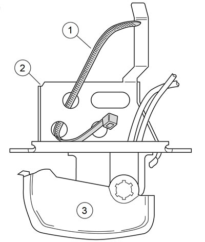
1. See Figure 6-151. Insert tapered end of new 7.0 in (177.8 mm) cable strap (1) into round hole in turn signal switch bracket (2) and then feed back through using the adjacent hole. Reserve the oblong hole for the bracket screw.

Figure 6-151. Insert cable strap in switch bracket: 1. Cable strap; 2. Bracket; 3. Left turn signal switch
Note. Be sure that all splices are positioned above the turn signal switch bracket.
2. Aligning the oblong hole in the bracket with the threaded hole in the boss. Place the turn signal switch assembly (3) into the housing. Fully seat the bracket. Tabs on each side of bracket are captured in slots cast into switch housing.
3. Start screw with lockwasher to secure bracket inside housing.
Notice: If routed incorrectly, wires can be pinched by casting or handlebar resulting in switch failure.
4. Loop switch wires so that spliced lengths are positioned across bracket.
5. Capturing conduit about 0.25 in (6.4 mm) from end, securely tighten cable strap to draw conduit to bracket. Trim cable straps.
6. Tighten screw to secure bracket inside housing.
7. Route wire bundle to upper switch housing below and then forward of the main wire harness.
8. Position conduit in channel next to angular arm of bracket. Secure bundle to arm using new cable strap.
9. Trim cable strap.
Installation
| FASTENER | TORQUE VALUE | |
| Handlebar control lever clamp screw | 108-132 in·lbs | 12.2-14.9Nm |
| Switch housing screw | 35-45 in·lbs | 4.0-5.1 Nm |
1. If the hand grip was removed, install a new hand grip. See 2.30 HANDLEBAR, Left Hand Grip.
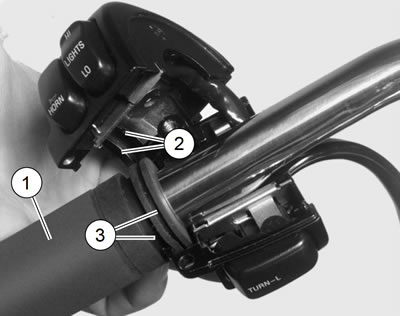
2. See Figure 6-152. Install upper and lower switch housings on handlebar. Be sure that ribs (2) on outboard side of switch housings fit in grooves (3) molded into grip.

Figure 6-152. Left handlebar switch housings: 1. Grip sleeve; 2. Ribs; 3. Grooves
3. Verify that the wire harness conduit runs in the groove at the bottom of the handlebar. Do not pinch the upper switch housing harness under the handlebar when the switch housing screws are tightened.
4. Start the upper and lower switch housing screws, but do not tighten.
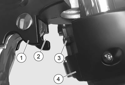
5. See Figure 6-153. Position the clutch hand lever assembly inboard of the switch housing assembly, engaging the tab (3) on the lower switch housing in the groove (2) at the bottom of the clutch lever bracket.

Figure 6-153. Clutch lever bracket: 1. Clutch lever bracket; 2. Groove; 3. Tab; 4. Switch housing assembly
6. Align the holes in the handlebar switch clamp with the clutch lever bracket. Start the two screws with flat washers. Position for rider comfort. Beginning with the top screw, tighten screws to specification with a T27 TORX drive head. Refer to Table 6-10.
7. Using a T25 TORX drive head, tighten lower and upper switch housing screws to specification. Refer to Table 6-10.
Note. Tighten the lower switch housing screw first. The gap between the upper and lower housings is at the front of the switch.
Table 6-10. Handlebar switch assembly fasteners
| FASTENER | TORQUE |
| Handlebar clamp screw | 108-132 in·lbs (12.2-14.9Nm) |
| Switch housing screws | 35-45 in·lbs (4.0-5.1 Nm) |
8. Install main fuse.
9. Verify the operation of the clutch interlock switch. See the electrical diagnostic manual.
Warning! Be sure that all lights and switches operate properly before operating motorcycle. Low visibility of rider can result in death or serious injury.
10. Test the switches for proper operation.
11. Secure wire harness to handlebar as necessary.
