
| PART NO. | SPECIALTY TOOL |
| HD-45314 | Crankshaft rotating wrench |
| HD-45653 | TDC positioning tool |
| HD-45306 | Crankshaft locking pin |
| HD-45491 | Tappet compressing tool |
1. Remove plug top coils and spark plugs. See 1.19 Spark plug/coil.
2. Remove cam cover.
3. See Figure 3-18. Install TDC POSITIONING TOOL (HD-45653) in front spark plug hole.
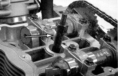
Figure 3-18. Top dead center positioning tool
Caution! Never insert a foreign object, such as a screwdriver, in the spark plug hole. Engine damage can result.
Caution! DO NOT ROTATE ENGINE CLOCKWISE. This is opposite the normal engine operation. Engine damage can result.
4. Using CRANKSHAFT ROTATING WRENCH (HD-45314) rotate the engine counter-clockwise (direction of operation). Note when exhaust valve is closing (TDC positioning tool will start to extend as valve closes) and engine is approaching TDC.
5. See Figure 3-19. When the TDC reference tool is fully extended, remove plug from timing hole on right side of engine and insert CRANKSHAFT LOCKING PIN (HD-45306).
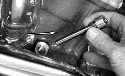
Figure 3-19. Crankshaft locking pin
6. The crankshaft locking pin should insert flush with engine case. It may be necessary to gently rock the crankshaft using the CRANKSHAFT ROTATING WRENCH (HD-45314) to lock engine at exact TDC.
7. Remove TDC POSITIONING TOOL (HD-45653) from front spark plug hole.

Figure 3-20. Cam drive: 1. Primary chain hydraulic tensioner; 2. Primary chain fixed guide; 3. Secondary chain tensioner; 4. Front cylinder fixed guide; 5. Rear cylinder fixed guide; 6. Front secondary cam chain; 7. Rear secondary cam chain; 8. Primary cam chain
8. See Figure 3-21. Holding 36 mm rotor nut with CRANKSHAFT ROTATING WRENCH (HD-45314), loosen rotor fastener. Air impact tool may be used for REMOVAL ONLY.
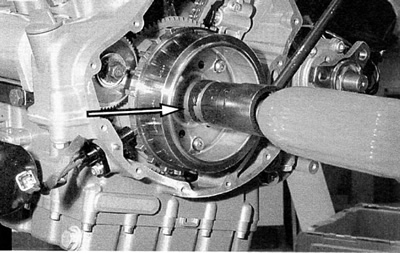
Figure 3-21. Rotor fastener
9. See Figure 3-22. Holding 36 mm rotor nut with CRANKSHAFT ROTATING WRENCH (HD-45314), loosen starter limiter fastener.

Figure 3-22. Starter limiter fastener
10. See Figure 3-23. Loosen triple sprocket fastener.
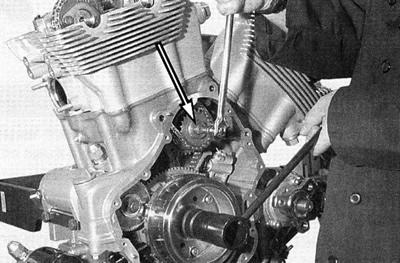
Figure 3-23. Triple sprocket fastener
11. See Figure 3-24. Remove rotor shell.
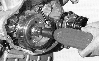
Figure 3-24. Rotor shell
12. See Figure 3-25. Remove starter limiter fastener and starter limiter gear assembly.
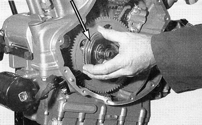
Figure 3-25. Starter limiter gear assembly
Warning! Always wear proper eye protection when removing retaining rings. Use the correct retaining ring pliers. Verify that the tips of the pliers are not excessively worn or damaged. Slippage may propel the ring with enough force to cause an accident. This could result in death or serious injury.
13. See Figure 3-26. Remove snap ring from crankshaft.
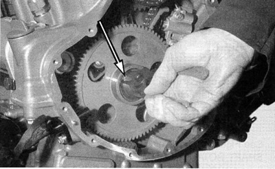
Figure 3-26. Snap ring
14. See Figure 3-27. Slide snap ring, washer, and gear ball clutch with needle roller and cage assembly off of crankshaft.
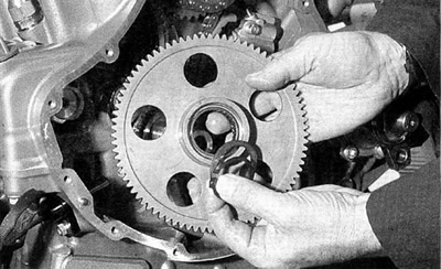
Figure 3-27. Snap ring removal
15. See Figure 3-28. For this procedure, the front cylinder cams are pre-loaded. Install TAPPET COMPRESSING TOOL (HD-45491) on front cylinder to aid in dissassem-bly.
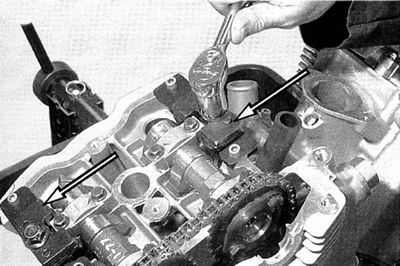
Figure 3-28. Tappet compressing tools (HD-45491)
- a. Loosen 19 mm nut on tappet compressing tool.
- b. Tools are marked intake and exhaust. Position them accordingly.
- c. Use M6x25 fasteners to secure tools to head.
- d. Tighten 19 mm nut to compress tappets.
16. See Figure 3-29. Remove secondary cam chain tensioner.
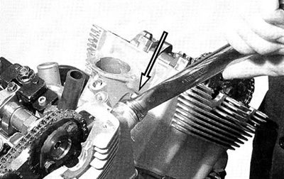
Figure 3-29. Remove secondary cam chain tensioner
17. See Figure 3-30. Remove cam bearing caps.
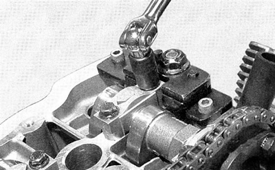
Figure 3-30. Cam bearing cap removal
18. See Figure 3-31. Roll chain over cam drive gear. Lift cam and drive gear from head.

Figure 3-31. Cam drive chain
19. In this position the rear cams are not preloaded. Remove rear cylinder bearing caps. Disconnect cams from chain.
20. Remove chains.
21. Remove water pump cover.
22. See Figure 3-32. Remove water pump housing. Using a soft face hammer, GENTLY tap around edge of housing while exerting outward pressure.

Figure 3-32. Removing water pump housing
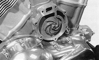
Figure 3-33. Water pump impeller/bearing housing

Figure 3-34.
23. See Figure 3-35. Retract primary cam chain tensioner and insert PRIMARY CAM CHAIN TENSIONER RETAINER (HD-45326). Remove primary cam chain tensioner.

Figure 3-35. Primary chain tensioner retainer (HD-45326)
24. See Figure 3-36. Remove primary cam chain fixed guide.
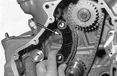
Figure 3-36. Primary chain fixed guide
25. See Figure 3-37. Remove the triple sprocket fastener.

Figure 3-37. Triple sprocket fastener
26. See Figure 3-38. Push triple sprocket/water pump shaft through engine toward the clutch side.

Figure 3-38. Triple sprocket/water pump shaft
27. See Figure 3-39. Remove triple sprocket and primary cam chain.
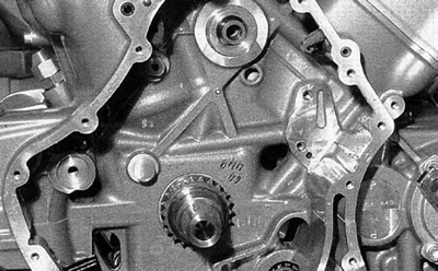
Figure 3-39. Triple sprocket and primary cam chain removed