| PART NO. | NEWAY NO. | SPECIALTY TOOL |
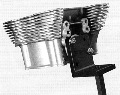
| HD-45333 | Cylinder head holder | |
| HD-39786 | Cylinder head holding fixture | |
| HD-35758-51 | 6 mm pilot | |
| HD-35758-53 | 203 | 46731° Exhaust seat cutter |
| HD-35758-54 | 271 | 70° Intake seat cutter |
| HD-35758-A | 622 | 46°/31° Intake seat cutter |
| HD-34751 | Cleaning brush |
Note. Verify correct valve stem to valve guide clearance before re facing. See Table 3-6. If new guides must be installed, complete that task before refacing valves and seats.
Note. This procedure is not based on the lapping of valves. The end result is an interference fit between the valve of 45 and the valve seat which will be 45.
1. See Figure 3-58. Use CYLINDER HEAD HOLDING FIXTURE (HD-39786) and CYLINDER HEAD HOLDER (HD-45333) to secure cylinder head for service.

Figure 3-58. Cylinder head holder
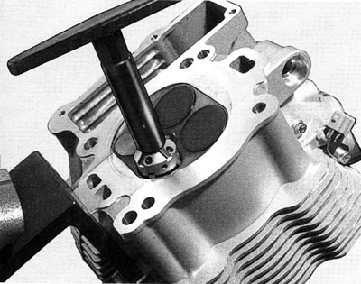
2. From the NEWAY VALVE SEAT CUTTER SET (HD-35758A) use #622 and cut intake (#203 for exhaust) valve seat angle to 46°. Do not remove any more metal than is necessary to clean up the seat (that is, to provide a uniform finish and remove pitting).
3. In order to determine the correct location of the 46° valve seat in the head, measure the width of the valve to be used and subtract 1.02 mm (0.040 in.) from that number.
4. Set your dial caliper to the lesser measurement and lock down for quick reference. This is the location of your valve seat.
5. Use a permanent magic marker to highlight the valve seat area that is going to be cut and be sure to highlight all 3 angles. Allow marker to dry before proceeding.

Figure 3-59. Mark valve seat
Note. Always ensure cutter blades and cutter pilot are clean before beginning the cutting process. The correct cleaning brush is supplied with the Neway tool set. Also ensure the inside of the valve guide is clean by using Kent-Moore CLEANING BRUSH (HD-34751).

Figure 3-60. Neway cutter
6. Choose the cutter pilot that fits properly into the valve guide hole and securely seat the pilot by pushing down and turning using the installation tool supplied in the tool set.
7. Choose the proper 46° cutter (intake or exhaust) and gently slide the cutter onto the pilot being careful not to drop the cutter onto the seat.
8. While applying a constant and consistent pressure, remove just enough material to show a complete cleanup on the 46° angle.
Note. If the width of the clean-up angle is greater on one side of the seat than the other, the guide may need to be replaced due to improper installation.
Note. After making the 46° cut, if you discover a groove cut completely around the seat this means the blades of the cutter are in alignment and need to be staggered. This is accomplished by loosening all of the blades from the cutter body and moving each blade slightly in it’s cradle in opposite directions on the cutter. The tool needed to loosen the blades is supplied in the tool set. A permanent magic marker mark every 90° will help in determining where new angles are.
9. Next, with your dial caliper locked to the predetermined setting, measure the 46° cut at the outer most edge at the widest point of the circle to determine what cut needs to be made next.
- a. If the 46° cut is to high (towards the combustion chamber), use the 30° cutter to lower the valve seat closer to the port.
- b. If the 46° cut is too low, and the width of the valve seat is too wide, use the 70° (intake only) cutter to raise the valve seat or move it away from the port.
Note. Due to using the top measurement of our valve seat as a reference point it will usually be necessary to use the 31° cutter following the initial 46° cut.
Note. On Flevolution engines, do not cut the bottom angle on the exhaust seat.
Note. Always highlight the valve seat with the permanent magic marker in order to ensure the location of the 46 valve seat.
10. If the location of the valve seat is not correct, repeat steps 6 through 8.
11. When you accomplish a complete clean-up of the 46° angle and the width is at least 0.750 mm (0.029 in.) for intake or 1.050 mm (0.041 in.) for exhaust, proceed to the next step.
12. Select the proper 70° cutter (for intake) and gently slide the cutter down the cutter pilot to the valve seat. The exhaust does not have a bottom angle.
13. See Figure 3-57. Remove just enough material to provide the proper valve seat width.

Figure 3-57. Valve and seat dimensions
14. Remove cutter pilot and wash head thoroughly and dry completely.
15. Repeat the process on any valve seat that needs service.
16. Insert valve to be used in the valve guide and bottom on the valve seat. Positioning the cylinder head port upwards and with slight thumb pressure against the valve, completely fill the port with solvent to verify proper seal between the valve and the valve seat.
Note. Hold pressure against the valve fora minimum of 10 seconds. If any leakage occurs, examine the valve seat for irregularities or defects and if necessary repeat the above cutting process.
