
Note: The oil cooler and distributor can be removed with the engine in the frame. If the engine has been removed, ignore the steps which do not apply.
Oil cooler
Removal
1. The cooler is located on the front of the engine on the left-hand side. Remove the stone guard, and the belly pan (see Chapter 8). To prevent the possibility of damage should a tool slip, it Is advisable to remove the left-hand fairing side panel as well (see Chapter 8).
2. Drain the engine oil (see Chapter 1). Keep the oil container handy to catch any residue oil from the cooler.
3. To remove the cooler without its feed and return pipes, unscrew the bolts securing the hose unions to the cooler and detach the hoses. Discard the О-rings as new ones must be used. Now unscrew the cooler mounting bolts, noting the collars, and remove the cooler (see illustration).
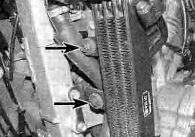
7.3. Oil cooler mounting bolts (arrowed)
4. To remove the cooler with its feed and return pipes, first remove the front sprocket cover (see Chapter 6). Unscrew the bolts securing the pipe retaining plate to the oil distributor on the crankcase and remove the plate, noting how it fits (see illustration). Unscrew the pipe guide bolts, then carefully pull the pipe ends out of the distributor (see illustration). Discard the О-rings as new ones must be used. Now unscrew the cooler mounting bolts, noting the collars, and remove the cooler and pipes (see illustration 7.3).
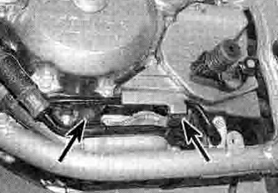
7.4a. Unscrew the pipe retaining plate bolts (arrowed)...

7.4b ...and the pipe guide bolts (arrowed)
5. To remove the pipes but leave the cooler In place, unscrew the bolts securing the hose unions to the cooler. Unscrew the bolts securing the pipe retaining plate to the oil distributor on the crankcase and remove the plate, noting how it fits (see illustration 7.4a). Unscrew the pipe guide bolts, then carefully pull the pipe ends out of the distributor and off the cooler and remove them noting how they fit (see illustration 7.4b). Discard the O-rings as new ones must be used.
Inspection
6. Check the cooler fins for mud, dirt and insects, which may impede the flow of air through the radiator. If the fins are dirty, clean the cooler using water or low pressure compressed air directed through the fins from the inner side of the radiator. If the fins are bent or distorted, straighten them carefully with a screwdriver. If the air flow is restricted by bent or damaged fins over more than 20% of the cooler's surface area, replace the cooler with a new one.
Installation
7. Installation is the reverse of removal, noting the following:
- Always use new О-rings on the pipe unions and smear them with clean oil.
- Check the condition of the cooler mounting grommets and replace them if they are damaged or deteriorated.
- Tighten the cooler mounting bolts, pipe union and retaining plate bolts, and pipe guide bolts to the torque settings specified at the beginning of the Chapter.
- Fill the engine with oil (see Chapter 1).
Oil distributor
Removal
22. Drain the engine oil and remove the filter (see Chapter 1).
23. Remove the front sprocket cover (see Chapter 6). Unscrew the bolts securing the pipe retaining plate to the oil distributor on the crankcase and remove the plate, noting how it (its (see illustration 7.4a). Unscrew the pipe guide bolts, then carefully pull the pipe ends out of the distributor (see illustration 7.4b). Discard the О-rings as new ones must be used.
24. Unscrew the distributor bolt and remove the distributor, noting how it fits. Discard the О-ring as a new one must be used. Note the locating dowel and remove it for safekeeping if it is loose - it could be in either the crankcase or the distributor.
Installation
25. Smear a new О-ring with clean oil and fit it into the groove in the distributor. Fit the dowel into the crankcase if it was removed.
26. Install the distributor, making sure it locates correctly on the dowel and the o-ring stays in place, and tighten the bolt to the torque setting specified at the beginning of the Chapter.
27. Fit the oil cooler pipes, using new O-rings, and tighten the pipe retaining plate bolts and pipe guide bolts to the torque settings specified at the beginning of the Chapter (see illustrations 7.4a and b).
28. Fit a new oil filter and fill the engine with oil (see Chapter 1).