Note: To remove the cylinder barrels the engine must be removed from the frame.
Removal
1. Remove the engine from the frame (see Section 5), then remove the cylinder head(s) (see Section 12) and the cam chain guide blade(s) (see Section 11).
2. On XL600V models, if required, unscrew the bolt securing the coolant inlet pipe to the cylinder and remove it. Discard the О-ring as a new one must be used.
3. On XL650V and XRV750 models, release one of the clips securing the coolant joint collar that connects between the two cylinders (see illustration). Slide the collar either forwards or backwards (depending on which clip was removed) so that it is detached from the stub on one or other of the cylinders. If required, unscrew the bolt securing the coolant inlet union to the front cylinder and remove it. Discard the О-ring as a new one must be used.

15.3. Remove one of the clips (arrowed) and slide the joint collar across
4. Let the cam chain drop down into its tunnel. Lift the cylinder up off the studs, taking care not to allow the connecting rod to knock against the side of the crankcase once the piston is free (see illustration). If it is stuck, tap around its joint faces with a soft faced mallet to free it from the crankcase. Don't attempt to free the cylinder by inserting a screwdriver between it and the crankcase - you'll damage the sealing surfaces. When the cylinder has been removed, stuff clean rags around the piston to prevent anything falling into the crankcase.
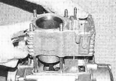
15.4. Lift the barrel up off the crankcase and remove it
5. Note the location of the two dowels which will be either on the bottom of the cylinder or in the crankcase (see illustration 15.19). Remove them if they are loose.
6. On XL650V and XRV750 models, remove the coolant joint collar from whichever barrel it is attached to, then remove the collar O-ring from the stub on each cylinder. Discard the О-rings as new ones must be used.
7. Remove the gasket and clean all traces of old gasket material from the cylinder and crankcase mating surfaces. If a scraper is used, take care not to scratch or gouge the soft aluminium. Don't let any gasket material fall into the crankcase or the oil passages.
Inspection
8. Do not attempt to separate the liner from the cylinder.
9. Check the cylinder bore walls carefully for scratches and score marks.
10. Using a precision straight-edge and a feeler gauge set to the warpage limit listed in the specifications at the beginning of the Chapter, check the top mating surface of the cylinder barrel for warpage. Refer to Tools and Workshop Tips in the Reference section for details of how to use the straight-edge. If warpage is excessive the cylinder must be replaced with a new one.
11. Using telescoping gauges and a micrometer (see Tools and Workshop Tips), check the dimensions of each cylinder bore to assess the amount of wear, taper and ovality. Measure near the top (but below the level of the top piston ring at TDC). centre and bottom (but above the level of the oil ring at BDC) of the bore, both parallel to and across the crankshaft axis (see illustrations). Compare the results to the specifications at the beginning of the Chapter. If the cylinders are worn, oval or tapered beyond the service limit they can be rebored, and an oversize (+ 0.25 or +0.50) set of pistons and rings are available from Honda. Note that the person carrying out the rebore must be aware of the piston-to-bore clearance for the oversize piston (see Specifications).
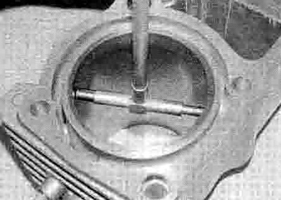
15.11a. Use a bore gauge...
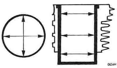
15.11b ...and measure at the points shown
12. If the precision measuring tools are not available, take the cylinders to a Honda dealer or specialist motorcycle repair shop for assessment and advice.
13. If the cylinder bores are in good condition and the piston-to-bore clearance is within specifications (see Section 16), the bores should be honed (de-glazed). To perform this operation you will need the proper size flexible hone with fine stones, or a bottle-brush type hone, plenty of light oil or honing oil, some clean rags and an electric drill motor.
14. Hold the cylinder sideways (so that the bore is horizontal rather than vertical) in a vice with soft jaws or cushioned with wooden blocks. Mount the hone in the drill motor, compress the stones and insert the hone into the bore. Thoroughly lubricate the cylinder walls, then turn on the drill and move the hone up and down In the bore at a pace which produces a fine cross-hatch pattern on the cylinder wall with the lines intersecting at an angle of approximately 60°. Be sure to use plenty of lubricant and do not take off any more material than is necessary to produce the desired effect. Do not withdraw the hone from the cylinder while it is still turning. Switch off the drill and continue to move it up and down in the cylinder until it has stopped turning, then compress the stones and withdraw the hone. Wipe the oil from the cylinder and repeat the procedure on the other one. Remember, do not take too much material from the cylinder wall.
15. Wash the bores thoroughly with warm soapy water to remove all traces of the abrasive grit produced during the honing operation. Be sure to run a brush through the stud holes and flush them with running water. After rinsing, dry the cylinders thoroughly and apply a thin coat of light, rust-preventative oil to all machined surfaces.
16. If you do not have the equipment or desire to perform the honing operation, take the cylinders to a Honda dealer or specialist motorcycle repair shop.
Installation
17. On XL650V and XRV750 models, fit a new О-ring onto the coolant joint collar stub on each cylinder, then slide the collar as far as possible onto the stub of one of them.
18. Check that the mating surfaces of the cylinder and crankcase are free from oil or pieces of old gasket.
19. If removed, fit the dowels either over the studs and into the crankcase or into the barrel, and push them firmly home (see illustration).
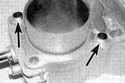
15.19. Install the two dowels (arrowed) either into the barrel or over the studs and into the crankcase
20. Remove the rags from around the piston, taking care not to let the connecting rod fall against the rim of the crankcase, and lay the new base gasket in place, locating it over the dowels (if they are in the crankcase) (see illustration). The gasket can only fit one way. so if the holes do not line up properly the gasket is upside down. Never re-use the old gasket.

15.20. Always use a new gasket
21. Space the piston rings gaps as described in Section 17. If required, fit a piston ring clamp onto the piston to ease its entry into the bore as the cylinder is lowered. This is not essential as there is a good lead-in, enabling the piston rings to be hand-fed into the bore. If possible, have an assistant support the cylinder while this is done.
22. Lubricate the cylinder bore, piston and piston rings with clean engine oil, then lower the barrel down over the studs until the piston crown fits into the bore (see illustration).
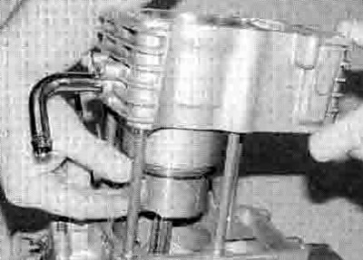
15.22. Carefully lower the barrel onto the piston...
23. Gently push the cylinder down, making sure the piston enters the bore squarely and does not get cocked sideways. If you are doing this without a piston ring clamp, carefully compress and feed each ring into the bore as the cylinder is lowered (see illustration).

15.23 ...and feed the piston rings into the bore
24. When the piston is correctly installed in the bore, press the cylinder down onto the base gasket, making sure the dowels locate. Hook the cam chain up the tunnel and secure It to prevent it dropping back down (see illustration).
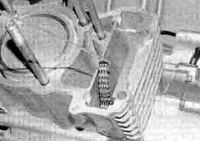
15.24. Hook the cam chain out of the tunnel
25. On XL600V models, if removed, fit a new О-ring onto the coolant inlet pipe, then fit it into the cylinder and secure it with the bolt.
26. On XL650V and XRV750 models, slide the coolant joint collar across and over the O-nng so that it is central on the stubs between the cylinders, then secure it in place with its clips (see illustration 15.3). If removed, fit a new О-ring to the coolant inlet hose union and install the union onto the front of the front cylinder, tightening its bolts securely.
27. Install the cam chain guide blade(s) (see Section 11) and the cylinder head(s) (see Section 12).
