
Caution: The engine must be completely cool before beginning this procedure or the cylinder heads may become warped.
Removal - front cylinder head
Note: The engine must be removed from the frame to enable removal of the front cylinder head.
1. Remove the engine from the frame (see Section 5).
2. Remove the valve cover (see Section 8).
3. Remove the spark plugs (see Chapter 1).
4. Remove the camshaft (see Section 9).
5. On XL600V-H to К (1987 to 1989) models, unscrew the bolts securing the external oil pipe and remove the pipe, noting how It fits and taking care not to bend it. Discard the sealing washers as new ones must be used.
6. Remove the cam chain tensioner (see Section 11).
7. The cylinder head is secured by four 10 mm nuts, one 8 mm nut (which on all except XL600V-H to К (1987 to 1989) models also secures the main camshaft holder and has therefore already been removed), two 8 mm bolts and one 6 mm bolt (see illustration). Slacken these evenly and a little at a time in a criss-cross pattern until they are all loose. Remove the nuts, bolts and washers. Take care not to drop any of the nuts or washers down the cam chain tunnel.
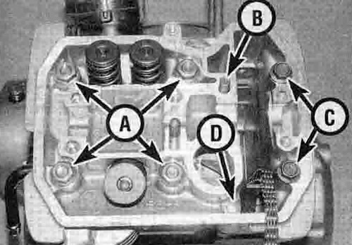
12.7. Cylinder head 10 mm nuts (A), 8 mm nut (B - see text), 8 mm bolts (C), 6 mm bolt (D)
8. Hold the cam chain up and pull the cylinder head up off the barrel, then pass the cam chain down through the tunnel (see illustration). Do not let the chain fall into the crankcase - secure It with a piece of wire or metal bar to prevent it from doing so. If it is stuck, tap around the base of the head with a soft-faced mallet to free it. Do not try to free the head by inserting a screwdriver between the head and cylinder barrel - you'll damage the sealing surfaces. Note that each head is marked 'F' or R' according to whether it is for the front or rear cylinder - the mark is located in the centre of the top of the head, between I he valves.
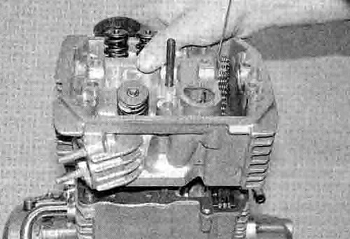
12.8. Carefully lift the head up off the barrel
9. Remove the old gasket (see illustration 12.22).
10. If they are loose, remove the two dowels from the cylinder barrel studs (see illustration 12.22). If either appears to be missing it is probably stuck in the underside of the cylinder head. If required, remove the cam chain guide blade from the front of the cam chain tunnel (see Section 11) (see illustration 11.13),
11. Check the cylinder head gasket and the mating surfaces on the cylinder head and barrel for signs of leakage, which could indicate warpage. Refer to Section 14 and check the cylinder head for warpage.
Caution: If you do not plan to remove the cylinder barrel, take care not to break the gasket joint between the barrel and the crankcase when cleaning the top surface of the barrel or pulling out the dowels. If the joint is broken the barrel must be removed (see Section 15) and the gasket renewed, otherwise oil leaks may result.
12. Clean all traces of old gasket material from the cylinder head and barrel. If a scraper is used, take care not to scratch or gouge the soft aluminium. Be careful not to let any of the gasket material fall into the crankcase, the cylinder bore or the oil passages. Unless you are removing the cylinder barrel, cover it with a clean rag to prevent any debris falling into the engine.
Removal - rear cylinder head
Note: On XL600V models the engine must be removed from the frame to enable removal of the rear cylinder head. On XL650V and XRV750 models removal of the rear cylinder head is possible with the engine in the frame.
13. On XL600V, remove the engine from the frame (see Section 5).
14. On XL650V and XRV750 models, drain the coolant (see Chapter 1). Remove the carburettors and the rear cylinder exhaust pipe (see Chapter 4).
15. Remove the spark plugs (see Chapter 1).
16. Remove the camshaft (see Section 9).
17. Remove the cam chain tensioner (see Section 11).
18. On XL600V-H to К (1987 to 1989) models, unscrew the bolts securing the external oil pipe and remove the pipe, noting how it fits and taking care not to bend it. Discard the sealing washers as new ones must be used.
19. The remainder of the procedure is the same as for the front cylinder - follow Steps 7 to 12 above.
Installation - both heads
20. If removed, fit the cam chain guide blade into the front of the cam chain tunnel (see Section 11) (see illustration 11.15).
21. If removed, fit the two dowels over the cylinder barrel studs and into the barrel (see illustration 12.22). Lubricate the cylinder bores with new engine oil.
22. Ensure both cylinder head and barrel mating surfaces are clean, then lay the new head gasket in place on the cylinder barrel, making sure it locates over the dowels (see illustration). The gasket can only fit one way. so if the holes do not line up properly the gasket is upside down. Never re-use the old gasket.

12.22. Install the dowels (arrowed) then lay the new gasket on the barrel
23. Make sure you have the correct head for the cylinder being worked on - the front head is marked 'F' and the rear 'R', with the mark located in the centre of the top of the head, between the valves. Carefully lower the cylinder head over the studs and onto the barrel (see illustration 12.8). It is helpful to have an assistant to pass the cam chain up through the tunnel and slip a piece of wire through it to prevent it falling back into the engine. Keep the chain taut to prevent it becoming disengaged from the crankshaft sprocket.
24. Install the 10 mm nuts with their washers, on XL600V-H to К (1987 to 1989) models the 8 mm nut with its washer, the 8 mm bolts with their washers and the 6 mm bolt; tighten them all finger-tight at this stage (see illustration 12.7). 2
25. Now tighten the cylinder head nuts and bolts evenly and a little at a time in a crisscross pattern to the torque settings specified at the beginning of the Chapter (see illustration).
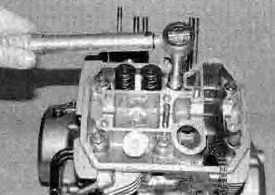
12.25. Tighten the nuts and bolts as described to the specified torque setting
26. Install all other components that have been removed in a reverse of the removal procedure, referring to the relevant sections where necessary. On XL600V-H to К (1987 to 1989) models blow through the external oil pipe and its bolts using compressed air if available, then install the pipe using new sealing washers and tighten its bolts to the specified torque setting.
27. If removed, install the engine as described in Section 5.