Note: The cam chains can be removed with the engine in the frame.
Front cylinder cam chain
Removal
1. Drain the engine oil (see Chapter 1).
2. Remove the alternator rotor (see Chapter 9).
3. Remove the camshaft (see Section 9). Remove the cam chain tensioner (see Section 11).
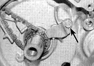
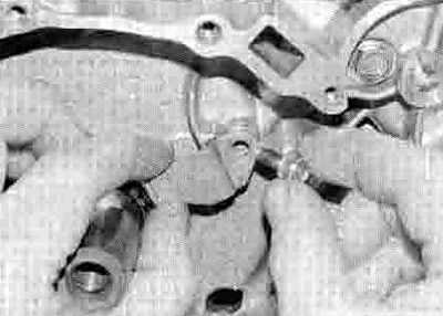
4. Unscrew the bolt securing the cam chain tensioner set plate to the crankcase and remove the plate, noting how it fits (see illustration). Drop the cam chain down its tunnel and remove it from the end of the crankshaft (see illustration). If difficulty is experienced in manoeuvring the chain past the cam chain guide blade, remove the cylinder head and lift the guide blade out of the crankcase.

10.4a. Unscrew the bolt (arrowed) and remove the plate

10.4b. Slip the chain down the tunnel and off the shaft
5. Check the sprocket teeth on the crankshaft for wear and damage. The teeth are integral with the crankshaft, so if any significant wear or damage Is found, the crankshaft must be replaced with a new one.
Installation
6. Hook the new cam chain onto a piece of wire and draw the chain up through its tunnel, making sure its bottom end engages around the sprocket on the crankshaft (see illustration 10.4b). Secure the chain at the top to prevent it falling back down the tunnel.
7. If removed, install the cam chain guide blade and cylinder head. Install the cam chain tensioner set plate, then apply a suitable nonpermanent thread-locking compound to its bolt and tighten it securely (see illustration).

10.7. Apply a locking compound to the retainer plate bolt threads
8. Install the cam chain tensioner (see Section 11).
9. Install the alternator/starter clutch assembly (see Section 21). Replenish the engine oil (see Chapter 1).
Rear cylinder cam chain
Removal
10. Drain the engine oil (see Chapter 1).
11. Remove the camshaft (see Section 9). Remove the cam chain tensioner (see Section 11).
12. On XL models, remove the ignition pulse generator coil(s) (sec Chapter 5).
13. Remove the clutch and primary drive gear (see Section 18).
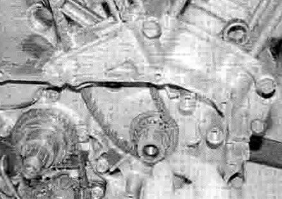
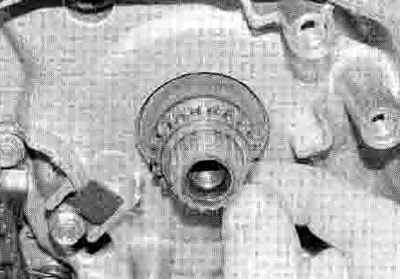
14. Drop the cam chain down its tunnel, then slide the sprocket towards the end of the shaft so that the chain clears the guide blade and remove it from the sprocket (see illustration). Slide the cam chain sprocket off the end of the crankshaft, noting which way around it is fitted, and check it for wear or damage to both the outer teeth and the inner splines (see illustration). If difficulty is experienced in manoeuvring the chain past the cam chain guide blade, remove the cylinder head and lift the guide blade out of the crankcase.

10.14a. Slide the sprocket out and remove the chain...

10.14b ...then remove the sprocket
Installation
15. Align the extra wide spline on the crankshaft with that on the sprocket, then slide the sprocket part-way onto the crankshaft the same was around as noted on removal (see illustration). Hook the new cam chain onto a piece of wire and draw the chain up through its tunnel, making sure its bottom end engages around the sprocket (see illustration 10.14a) Slide the sprocket home and secure the chain at the top to prevent it falling back down the tunnel. If removed, install the cam chain guide blade and cylinder head.

10.15. Align the wide spline on the sprocket (A) with that on the shaft (B)
16. Install the primary drive gear and clutch (see Section 18).
17. On XL models, install the ignition pulse generator coil(s) (see Chapter 5).
18. Install the cam chain tensioner (see Section 11) and the camshaft (see Section 9). Replenish the engine oil (see Chapter 1).
