
2. Lay out the pistons and the new ring sets so the rings will be matched with the same piston and bore during the end gap measurement procedure and engine assembly.
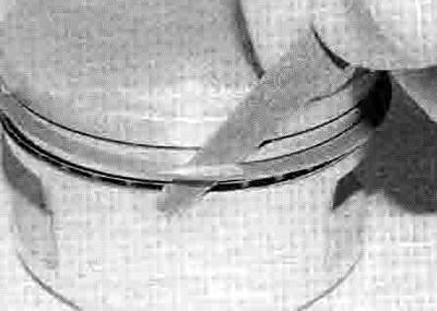
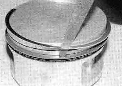
3. To measure the installed ring end gap, insert the top ring into the top of the bore and square it up with the bore walls by pushing it in with the top of the piston (see illustration). The ring should be about 20 mm below the top edge of the bore. Slip a feeler gauge between the ends of the ring and compare the measurement to the specifications at the beginning of the Chapter (see illustration).
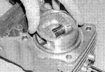
17.3a. Fit the ring into the bore and square it up with the piston
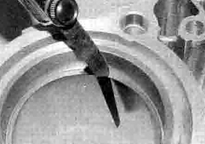
17.3b. Measuring piston ring end gap
4. If the gap is larger or smaller than specified, double check to make sure that you have the correct rings before proceeding.
5. Excess end gap is not critical unless it exceeds the service limit. Again, doublecheck to make sure you have the correct rings for your engine and check that the bore is not worn (see Section 15).
6. Repeat the procedure for each ring that will be installed in the bore. Remember to keep the rings, pistons and bores matched up.
7. Once the ring end gaps have been checked the rings can be installed on the pistons (see illustration 17.12).
8. Install the oil control ring (lowest on the piston) first. It is composed of three separate components, namely the expander and the upper and lower side rails. Slip the expander into the groove, making sure the ends don't overlap, then install the lower side rail (see illustrations). Do not use a piston ring installation tool on the side rails as they may be damaged. Instead, place one end of the side rail into the groove between the expander and the ring land. Hold it firmly in place and slide a finger around the piston while pushing the rail into the groove. Next, install the upper side rail in the same manner (see illustration). Check that the ends of the expander have not overlapped.
17.8a. Install the oil ring expander in its groove...

17.8b ...then fit the lower side rail...
17.8c ...and the upper side rail
9. After the three oil ring components have been installed, check to make sure that both the upper and lower side rails can be turned smoothly in the ring groove.
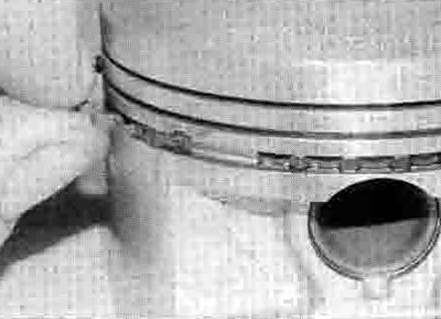
10. The upper surface of the top ring is marked with the letter R or N at one end. and the second (middle) ring is either marked RN or •, or is unmarked (see illustration 16.4), The top and middle rings can also be identified by their different profiles (see illustration 17.12). Install the second (middle) ring next. Make sure that the identification letter near the end gap is facing up. or if the ring is unmarked make sure the wider edge is at the bottom, as shown in the illustration of the profile (see illustration 17.12). Fit the ring into the middle groove in the piston (see illustration). Do not expand the ring any more than is necessary to slide it into place. To avoid breaking the ring, use a piston ring installation tool, or alternatively a feeler gauge blade can be used as shown.
17.10. Fit the middle ring into its groove...
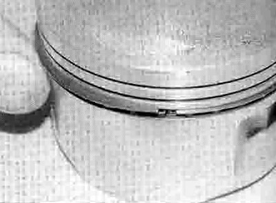
11. Finally, install the top ring in the same manner into the top groove in the piston (see illustration). Make sure the identification letter near the end gap is facing up.
17.11 ...then fit the top ring
12. Once the rings are correctly installed, check they move freely without snagging and stagger their end gaps as shown (see illustration).

17.12 Arrange the ring end gaps like this: 1. Top compression ring; 2. Compression ring marking (see text); 3. Second compression ring; 4. Oil ring complete; 5. Expander ring; 6. Side rails