Electrical parts
Connector/coupler
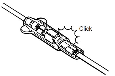
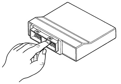
- When connecting a connector, be sure to push it in until a click is felt.
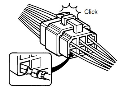
- With a lock type coupler, be sure to release the lock when disconnecting, and push in fully to engage the lock when connecting.
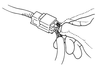
- When disconnecting the coupler, be sure to hold the coupler body and do not pull the lead wires.
- Inspect each terminal on the connector/coupler for looseness or bending.
- Inspect each terminal for corrosion and contamination. The terminals must be clean and free of any foreign material which could impede proper terminal contact.
- Inspect each lead wire circuit for poor connection by shaking it by hand lightly. If any abnormal condition is found, repair or replace.
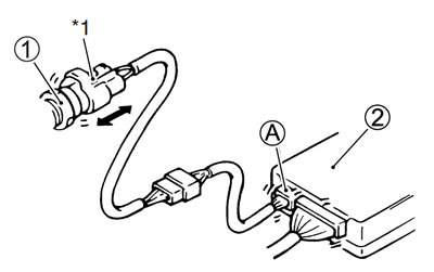
- When taking measurements at electrical connectors using a tester probe, be sure to insert the probe from the wire harness side (backside) of the connector/coupler.
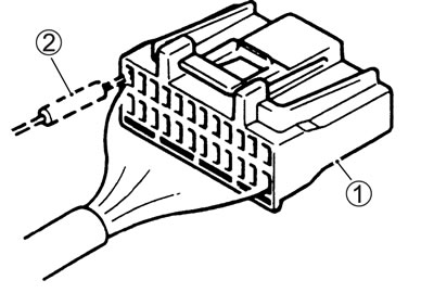
1. Coupler; 2. Probe
- When connecting meter probe from the terminal side of the coupler (where connection from harness side not being possible), use extra care not to force and cause the male terminal to bend or the female terminal to open.
- Connect the probe as shown to avoid opening of female terminal.
- Never push in the probe where male terminal is supposed to fit.
- Check the male connector for bend and female connector for excessive opening. Also check the coupler for locking (looseness), corrosion, dust, etc.
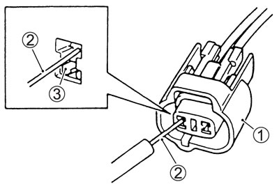
1. Coupler; 2. Probe; 3. Where male terminal fits
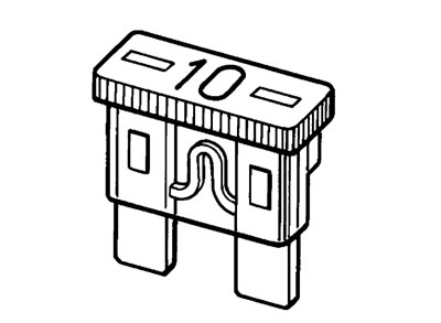
Fuse
- When a fuse blows, always investigate the cause to correct it and then replace the fuse.
- Do not use a fuse of a different capacity.
- Do not use wire or any other substitute for the fuse.
ECM/Various sensors
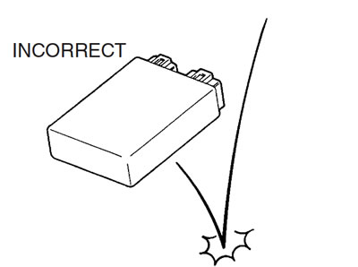
- Since each component is a high-precision part, great care should be taken not to apply any sharp impacts during removal and installation.
- Be careful not to touch the electrical terminals of the ECM. The static electricity from your body may damage this part.
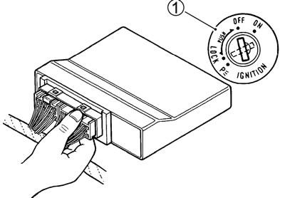
- When disconnecting and connecting the ECM, make sure to turn OFF the ignition switch 1, or electronic parts may get damaged.
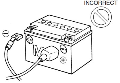
- Battery connection in reverse polarity is strictly prohibited. Such a wrong connection will damage the components of the FI system instantly when reverse power is applied.
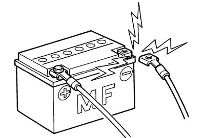
- Removing any battery terminal of a running engine is strictly prohibited. The moment such removal is made, damaging counter electromotive force will be applied to the ECM which may result in serious damage.
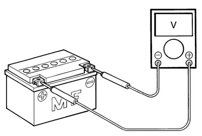
- Before measuring voltage at each terminal, check to make sure that battery voltage is 11 V or higher. Terminal voltage check with a low voltage battery will lead to erroneous diagnosis.
- Never connect any tester (voltmeter, ohmmeter, or whatever) to the ECM when its coupler is disconnected.
- Therwise, damage to ECM may result.
- Never connect an ohmmeter to the ECM with its coupler connected. If attempted, damage to ECM or sensors may result.
- Be sure to use a specified voltmeter/ohmmeter. Otherwise, accurate measurements may not be obtained and personal injury may result.
Electrical circuit inspection procedure
- While there are various methods for electrical circuit inspection, described here is a general method to check for open and short circuit using an ohmmeter and a voltmeter.
Open circuit check
Possible causes for the open circuits are as follows. As the cause can exist in the connector/coupler or terminal, they need to be checked carefully.
- Loose connection of connector/coupler.
- Poor contact of terminal (due to dirt, corrosion or rust, poor contact tension, entry of foreign object etc.).
- Wire harness being open.
- Poor terminal-to-wire connection.
- Disconnect the negative cable from the battery.
- Check each connector/coupler at both ends of the circuit being checked for loose connection. Also check for condition of the coupler lock if equipped.
1. Sensor; 2. ECM; *1. Check for loose connection.
- Using a test male terminal, check the female terminals of the circuit being checked for contact tension.
- Check each terminal visually for poor contact (possibly caused by dirt, corrosion, rust, entry of foreign object, etc.). At the same time, check to make sure that each terminal is fully inserted in the coupler and locked.
- If contact tension is not enough, rectify the contact to increase tension or replace.
- The terminals must be clean and free of any foreign material which could impede proper terminal contact.
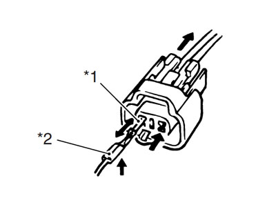
*1 Check contact tension by inserting and removing; *2 Check each terminal for bend and proper alignment.
- Using continuity inspect or voltage check procedure as described below, inspect the wire harness terminals for open circuit and poor connection. Locate abnormality, if any.
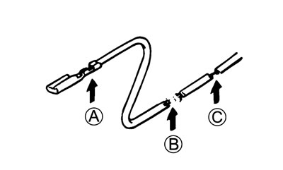
А. Looseness of crimping; В. Open; С. Thin wire (a few strands left)
Continuity check
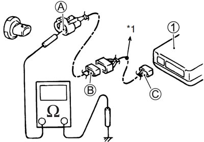
- Measure resistance across coupler В (between А and С in the figure).
- If no continuity is indicated (infinity or over limit), the circuit is open between terminals А and С.
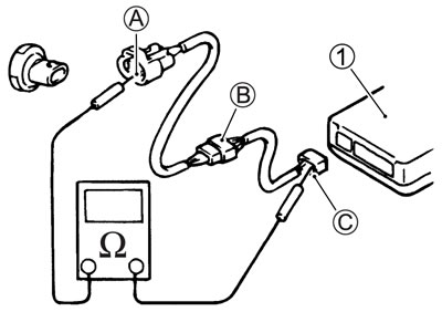
1. ECM
- Disconnect the coupler В and measure resistance between couplers А and В.
- If no continuity is indicated, the circuit is open between couplers А and В. If continuity is indicated, there is an open circuit between couplers В and С or an abnormality in coupler В or coupler С.
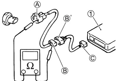
1. ECM
Voltage check
- If voltage is supplied to the circuit being checked, voltage check can be used as circuit check.
- With all connectors/couplers connected and voltage applied to the circuit being checked, measure voltage between each terminal and body ground.
- If measurements were taken as shown in the figure at the right and results are as listed below, it means that the circuit is open between terminals А and В.
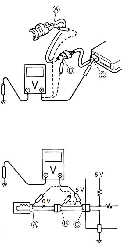
Voltage Between:
- С. and body ground: Approx. 5 V
- В. and body ground: Approx. 5 V
- А. and body ground: 0 V
Also, if measured values are as listed below, a resistance (abnormality) exists which causes the voltage drop in the circuit between terminals А and В.
Voltage Between:
- С. and body ground: Approx. 5 V
- В. and body ground: Approx. 5 V — 2 V voltage drop
- А. and body ground: 3 V — 2 V voltage drop
Short circuit check (wire harness to ground)
- Disconnect the negative cable from the battery.
- Disconnect the connectors/couplers at both ends of the circuit to be checked.
Note: If the circuit to be checked branches to other parts as shown, disconnect all connectors/couplers of those parts. Therwise, diagnosis will be misled.
- Measure resistance between terminal at one end of circuit (А terminal in figure) and body ground. If continuity is indicated, there is a short circuit to ground between terminals А and С.
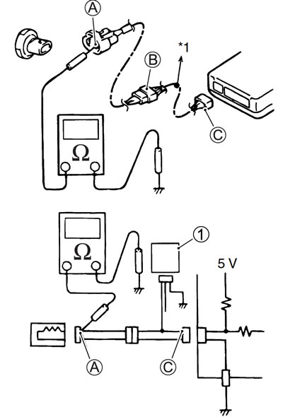
1. Other parts; *1. To other parts
- Disconnect the connector/coupler included in circuit (coupler В) and measure resistance between terminal А and body ground.
- If continuity is indicated, the circuit is shorted to the ground between terminals А and В.
1. ECM; *1. To other parts
Using the multi-circuit tester
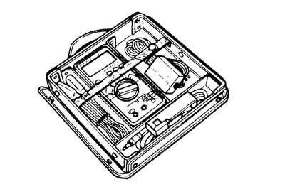
- Use the Suzuki multi-circuit tester set (09900-25008).
- Use well-charged batteries in the tester.
- Be sure to set the tester to the correct testing range.
Using the tester
- Incorrectly connecting the + and - probes may cause the inside of the tester to burnout.
- If the voltage and current are not known, make measurements using the highest range.
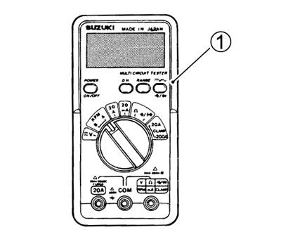
- When measuring the resistance with the multi-circuit tester 1, ∞ will be shown as 10.00 MΩ and "1" flashes in the display.
- Check that no voltage is applied before making the measurement. If voltage is applied the tester may be damaged.
- After using the tester, turn the power off.
- 09900-25008: Multi-circuit tester set
Note:
- When connecting the multi-circuit tester, use the needle pointed probe to the back side of the lead wire coupler and connect the probes of tester to them.
- Use the needle pointed probe to prevent the rubber of the water proof coupler from damage.
- 09900-25009: Needle pointed probe set